Assembly and operating instructions
CENTAX-L
016L-00050…00090-FS10
CENTA Antriebe Kirschey GmbH 35 / 46
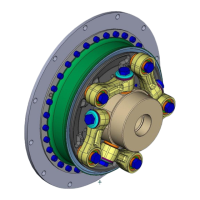
The recess must be pointing towards
the flange
PTFE coating must be at the top
Washer for centrifugal bearing
Dimensions as shown in parts
list
Dimensions as shown in parts
list
Set the link unit (1) marked "Flange" on the centring fixture of the
flange (3).
Position the link side with the inscription "Hub" against the centring
fixture of the hub/tube (2).
Tighten the screw (7; "Flange") with the washer (8; only at size 3 and 4)
and the screw (6; "Hub"), washer for centrifugal bearing (5) and the
bearing unit (4; PTFE coating must be at the top) alternately by hand
until the centring fixtures of the collar sleeves (1.1) are seated in the
centring fixtures of the hub/tube (2) / flange (3).
Repeat the mounting section above until all links are mounted (for quantity
of the links, please see the table guide to links).
Fasten the screws (6 and 7) of the link unit (1) by required tightening torque
"crosswise".