en-3
WIRING OF CONTROL BOARD
The cables for the power supply and the connected equipment are
routed from below into the sliding door operator through the rubber
seal at the bottom of the control covering.
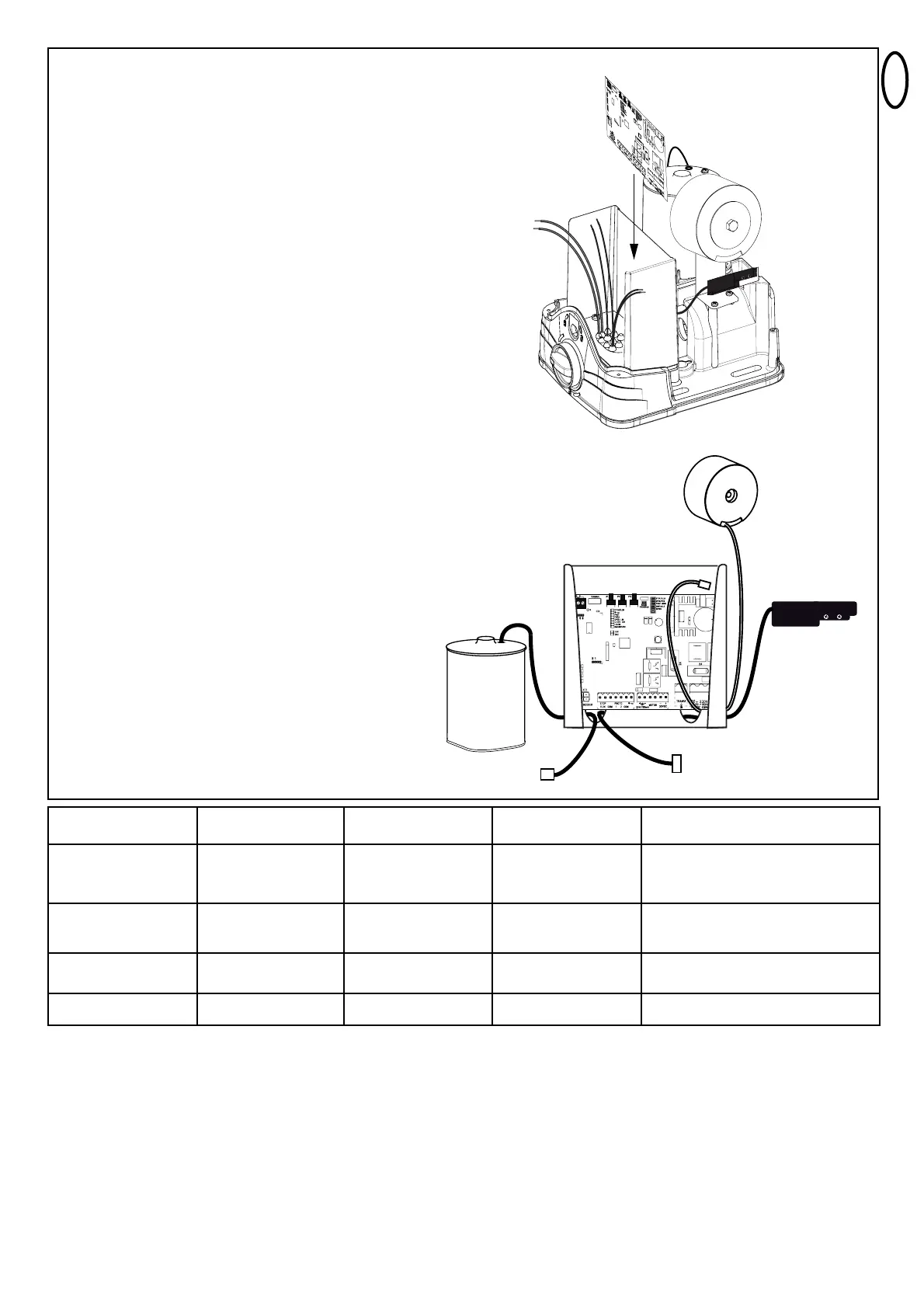
The controller is to be mounted with the terminal strips down as
shown in the picture.
Generally avoid:
- 230Volt and low voltage in the same power line. Not allowed by
electrical rules.
- Wiring of the photocells, switches, flashing lamps require a cable
separately from the motor wiring.
- Other wirings like telephone intercoms, lights for garden etc. must
be in separate cables.
- Rigid copper cables especially when thicker diameters are difficult
to manage during the installation and may result in bad
connections with functional issues. Use flexible cables instead.
- Cable material not suitable for outside use. Use cables suitable for
outside use and underground. Run the cables in conduits if the
cable is not suitable for placing in the ground (armoured or suitably
protected). You may also consult your local electrician.
Terminals:
The terminal blocks on the controller can be removed (pull) to
facilitate a convenient wiring and are pushed back only while
installing the controller. Even if a terminal strip is not in use, it must
be pushed back. The wiring is done as described in the wiring
diagram.
Plugs (available on the motor and the transformer):
These plugs must be connected to the controller (plugged in).
The cable of the connectors are not routed from below, but from the
back of the controller (see picture).
1. 230 Volt transformer feeder TRANSF IN and INPUT 24 VAC
2. Limit switch
3. Motor connector RPM/Encoder
Motor wiring:
connect to designated terminals as per wiring diagram
Radio:
The radio system is supplied as a small radio module separately
from the main controller and plugged in when needed as shown in
the wiring diagram. A short cable antenna is always pre-assembled
at the factory.
Wire sizes:
see chart
External antenna
(Remove original
antenna of logic board)
Switches, Flashing lamp
etc.
Photocells, safety edge
Power supply
Distance
0m - 6m
Coax cable (Satellite
cable)
50 or 75 Ohm
2x 0,5mm²
2x 0,5mm²
3x 0,72mm²
Distance
6m - 10m
Coax cable (Satellite
cable)
50 or 75 Ohm
2x 0,5mm²
2x 0,5mm²
3x 0,72mm²
Distance
10m - 12m
Coax cable (Satellite
cable)
50 or 75 Ohm
2x 0,75mm²
2x 0,75mm²
3x 1,5mm²
Distance
12m – xx
Coax cable (Satellite cable)
50 or 75 Ohm
(max. 25m)
Min. 2x 0,75mm²
Max. 30m
Min. 2x 0,75mm²
Max. 20m
3x 1,5mm²
1
2
3
Note:
The terminals are designed for a max. cable diameter of 1,5mm² (flexible wire).
See page 5 for
Description of
the terminals!