en-7
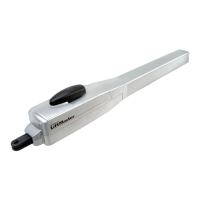
PHOTOCELLS (OPTIONAL) MODEL: 771E / 772E
The photocells are for safeguarding the gate and must be used.
The fitting location depends on the gate’s design. EN12453
specifies that a pair of photocells must be installed outside at a
height of 200 mm and activated to “Close”. The photocells consist of
a transmitter and a receiver and must be opposite each other. The
photocell is mounted on the wall using small screws and wall plugs.
Programming of IR sensors:
- connect IR sensors
- program the travel of the gate
Deletion of IR sensors:
Disconnecting already connected IR sensors will cause the control
board to block the functionality of the terminals it was connected to.
To delete IR sensors correctly:
- cut control board from current
- disconnect IR sensors
- program travel distance
- reconnect to power
Diagnosis of the photocell771E / 772E (772E with open cover)
LED constant = OK
LED flashes = photocell disables control board
LED off = no current, incorrect connection or polarity
Diagnosis on the control board LED PHO1 / PHO2
LED constant = OK
LED off = OK no photocell connected
LED flashes = photocell disables control board
Connection between 1 & COM:
Active when gate is closing (reverses gate to open)
Connection between 2 & COM:
adjustable:
Jumper “PHO 2 MODE” free >> active when gate is closing
Jumper “PHO 2 MODE” plugged >> active when gate is closing
and opening
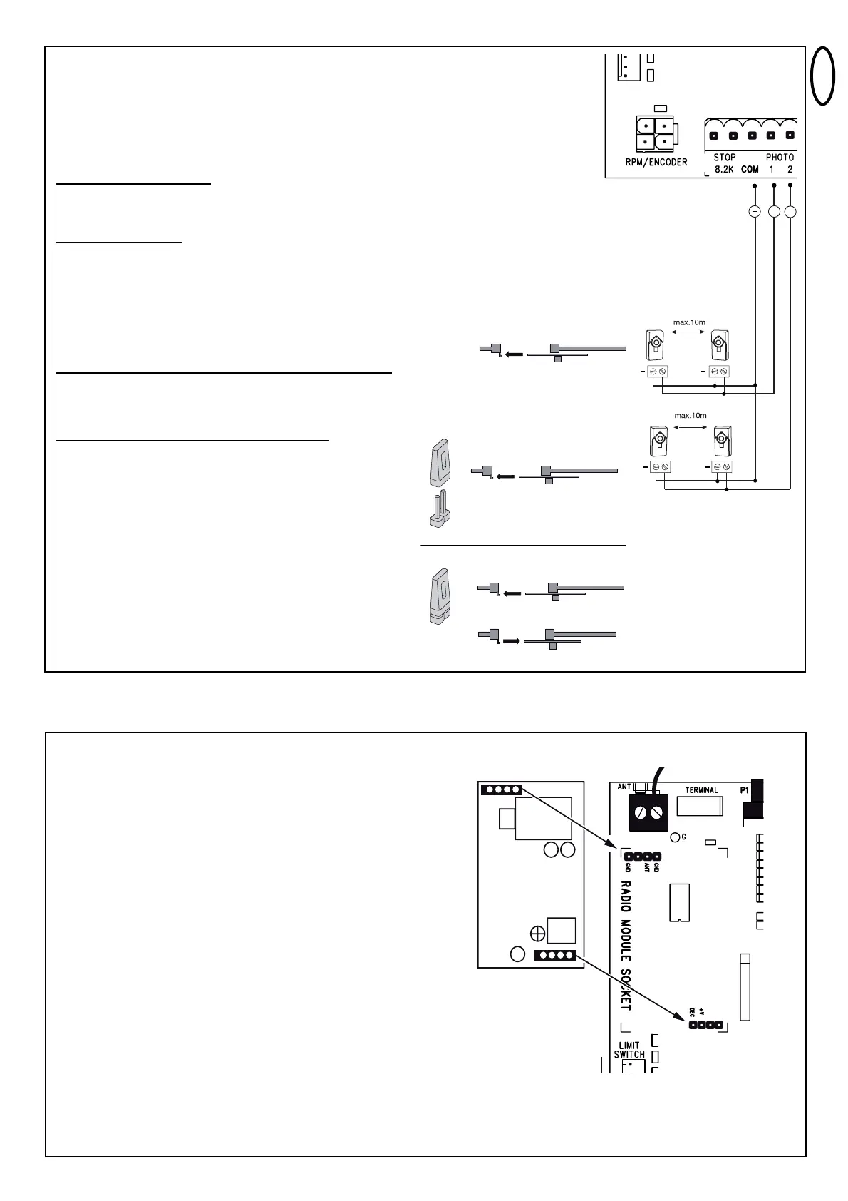
RADIO AND RADIO PROGRAMMING
Insert radio module on designated pins, if not pre-installed.
PROGRAM / DELETE REMOTE CONTROLS
The receiver has two channels CH1 and CH2.
The respective LEDs CH1 and CH2 are assigned to these two channels.
Receiving a signal from a programmed remote control button, CH1 fully
opens the gate.
Receiving a signal from another programmed remote control button,
CH2 partially opens the gate (pedestrian mode).
PROGRAMMING
1. Insert (connect) jumper “RADIO”
2. Briefly push button P1 (for CH1) or P2 (for CH2) and the respective
LED lights up.
3. Press and hold a selected button on your remote control until LED
goes out after short flashing. Done!
Repeat for all remote controls (a maximum of 180 remote controls
can be programmed to each channel).
Important: To finish programming, remove (disconnect) jumper “Radio”!
Note: Make sure not to program the same remote control button to
CH1 and CH2, otherwise the gate will work improperly.
DELETE
1. Insert (connect) Jumper “Radio”.
2. Press and hold buttons P1 (for CH1) or P2 (for CH2) until the
respective LED goes out again (approx. 10 seconds).
Single remote controls can not be deleted. All remotes programmed
to this channel are deleted.
Important: To finish deleting, remove (disconnect) jumper “Radio”