32
Components & Systems Product Manual - Orca
™
CO
2
Series MicroBulk Delivery System
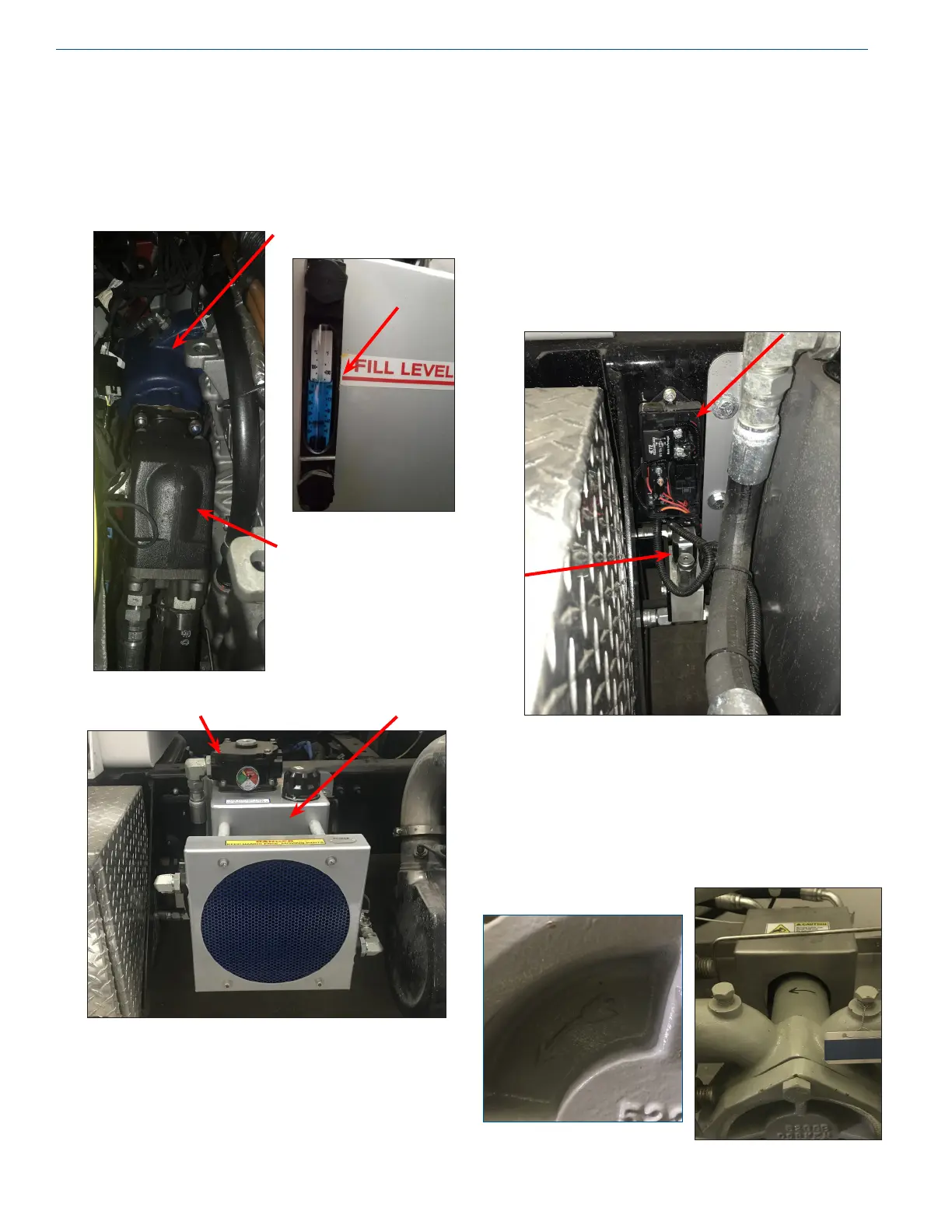
Hydraulic System - Truck
Power Take-O (A) is connected to hydraulic pump (B).
Ensure reservoir (C) is lled to proper height (D). Filter (E)
is located in the reservoir.
Hydraulic System cont.
The hydraulic electrical junction box (F) contains a fuse
and relays for powering solenoid block (G) and the cooling
fan. When the cabinet switch (SW-1) is in the up position,
recirculating ow is redirected to the motor (MTR-1) in the
cabinet to power the CO
2
pump (Pl-1). Both the junction
box and the solenoid block are located near the hydraulic oil
cooling reservoir.
See OEM manuals for further information.
Motor and CO
2
Pump Rotation
Direction
Cast onto the CO
2
Pump end cover is an arrow indicating the
pump rotation. The rotation is counterclockwise as viewing
this pump cover.
A
B
D
CE
F
G