NVF5 Series User Manual Chapter 6 Parameter Function Description
same time,the inverter will stop.
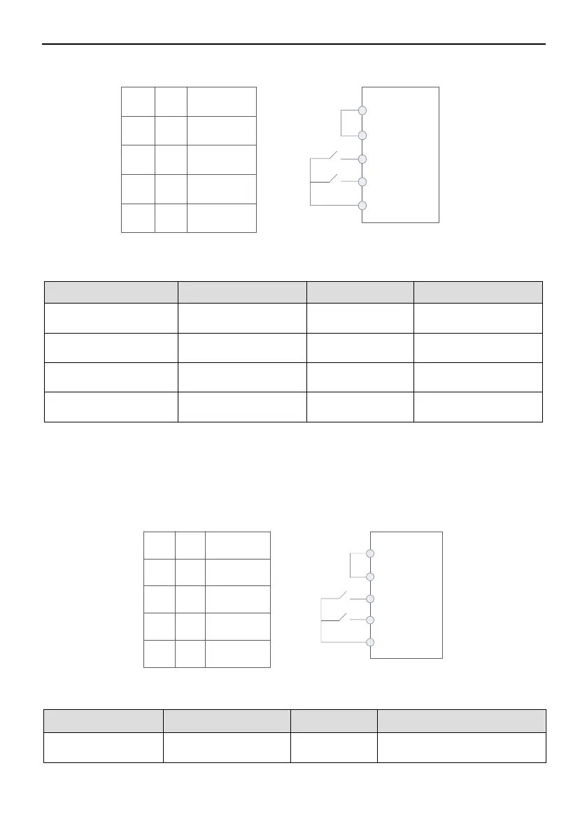
K1
K2
RUN
0
0
0
1
1
0
1
1
STOP
Run
Reverse
Run
Forward
STOP
+24V
PLC
DI1
DI2
COM
K1
K2
Figure 6-1-1 Two Wire Control Mode1
Parameters Setting as below:
F0.01
Command Channel
Selection
1 Terminal Control
F5.08
Terminal Control
Mode Selection
0
F5.01
1
Forward(FWD)
F5.02
2
Reverse(REV)
Two Wire Control Mode 2:
In this mode,DI1 is Run Enable input terminal,DI2 control the direction.Shown in the
below figure,in this mode when K1 is closed,K2 is opened,the inverter will run forward,
K2 is closed the inverter will run reverse;when K1 is opened,the inverter will stop.
K1
K2
RUN
0
0
0
1
1
0
1
1
STOP
STOP
Run
Forward
Run
Reverse
+24V
PLC
DI1
DI2
COM
K1
K2
Figure 6-1-2 Two Wire Control Mode2
Parameters Setting as below:
Command Channel
Selection
Terminal Control
- 39 -
Inverter
Inverter