NVF5 Series User Manual Chapter 6 Parameter Function Description
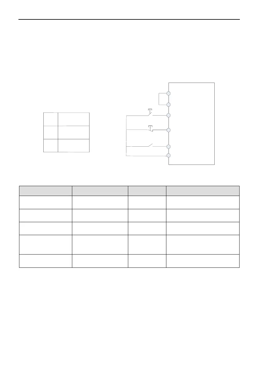
In this mode,DI3 is Run Enable input terminal,after Running command is given by
DI1,DI2 control the direction.As shown in the below figure,when SB1 is closed,when
pressing SB2 the inverter will start,when K is opened the inverter will run forward,when K
is closed the inverter will run reverse;when SB1 is opened the inverter will stop. In normal
Start and Running process,SB1 must be kept closed,SB2 will be took effect in rising
edge.
+24V
PLC
DI1
DI3
COM
SB2
DI2
SB1
K
K RUN
0
1
Run
Forward
Run
Reverse
Figure 6-1-4 Three Wire Control Mode2
Paremeters Setting as below:
Command Channel
Selection
Terminal Control
Mode Selection
Three Wire Control Mode 2
Forward(“Enable”)
Selection
Reverse(“FWD/REV
Switch”)
6.1.3 “Comm.”Setting Control
Set parameter F0.01=2,can realize Start、Stop command by Comm. control
NVF5 supports Modbus Communication mode. See Appendix A about Modbus
protocol description.
6.1.4 “Remote Keypad”Setting
Set parameter F0.01=3,when remote keypad is used,the inverter can be realized
RUN、STOP by remote keypad.When pressing RUN key,the inverter will start,RUN
indicator light;In running mode,press STOP key the inverter will stop,RUN indicator
light off.
- 41 -
Inverter