NVF5 Series User Manual Chapter 6 Parameter Function Description
F5.42
Curve 4 Break Point 2
Setting
60.0%
(-100.0~+100.0)%
Frequenc
y
F5.43
10.00V
F5.41 ~ +11.00V
F5.44
Curve 4 Max. Reference
Setting
100.0%
(-100.0~+100.0)%
AI Curve Selection:
The setting curves of the analog input terminals AI1 and AI2 are selected by the bits
and ten bits of the parameter F5.24. The bigger the filtering time of AI input, the stronger
the anti-interference ability, but the slower the adjusting response; the smaller the filtering
time, the faster the adjusting response, but the weaker the anti-interference ability.
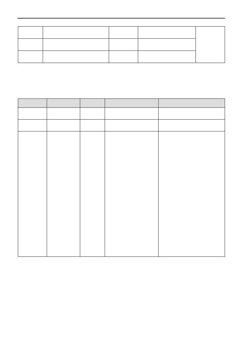
Code Name Default Setting Range Description
F5.21 AI1 Filter 0.10s
(0.00 ~ 10.00)s
-
F5.22 AI2 Filter 0.10s
(0.00 ~ 10.00)s
-
F5.24
Curve
Selection
0x0000
0x0000 ~ 0x3333
Ones Place:AI1 Curve
Selection
0:Curve1
1:Curve 2
2:Curve 3
3:Curve 4
Tens Place:AI2 Curve
Selection
0:Curve1
1:Curve2
2:Curve 3
3:Curve 4
Hundreds Place:Reserve
Thousandd Place:
6.2.4 HDI Main Frequency Setting
Set parameter F0.02=4,select HDI as main frequency reference. The pulse given can
only be selected by HDI,you can configure parameter F5.00 to realize.
The relationship between input pulse frequency and corresponding setting of HDI
terminal can be set by parameters F5.15 ~ F5.18. The correspondence is linear
relationship, and 100.0% of the pulse input is the percentage of the relative maximum
frequency F0.07.
- 46 -