Model 55,75,90, & HMC FLEX-AUGER Installation
21
MA1702D
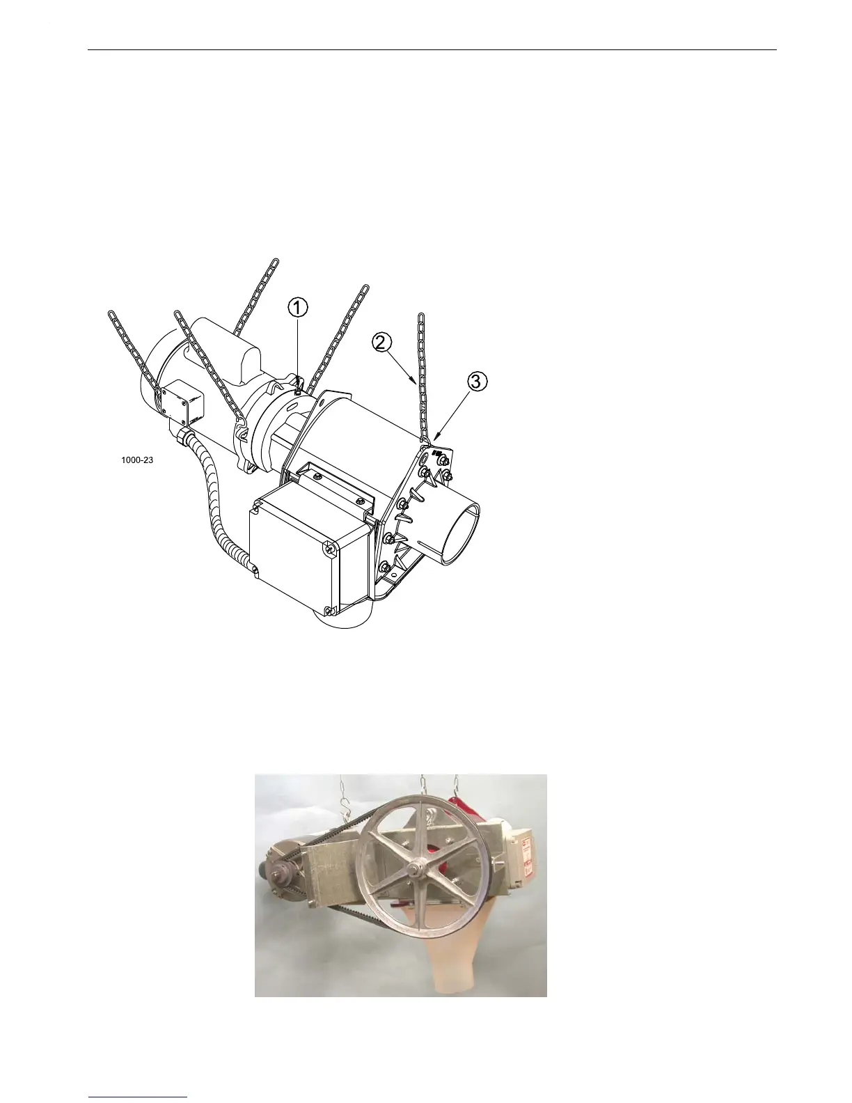
6.Support the Power Unit and Control Unit securely. Points are provided at the gear head and the tube anchor
for suspending the equipment with chain and “S” hooks supplied with the delivery system (See Figure 20).
NOTE: Other ways of supporting the delivery system can be used where it is practical, as long as the
supports do not let the equipment sag or do not make flat spots in the auger tubes.
Note:The motor should be fastened to keep it from twisting. "S" hooks and chain can be attached
to the motor base to prevent the motor from shifting.
7.Install the driver assembly on the power unit shaft. Start the socket head screws but leave the anchor clamp
loose enough to slip in the auger.
8.Replace the plastic shipping plug in the gear head with the vent plug provided.
Belt Drive Control Unit Installation
The Belt Drive Control Unit installation is much the same as the direct drive unit. Mount the Belt Drive Adapter
and Motor to the control unit, then proceed with installation to the auger tube as described in this manual.
“Standard Belt Drive Control Units” on page 40 can be used as an assembly guide for the Belt Drive Control
Unit. Figure 21 shows a Belt Drive Control Unit suspended.
Key Description
1 Replace shipping plug with
vent plug provided.
2 Chain
3“S” Hook
Figure 20.Control Unit/Power Unit Suspension
Figure 21.Belt Drive Control Unit