Model 55,75,90, & HMC FLEX-AUGER Installation
17
MA1702D
Long Elevated Systems
Outlet Assembly Installation
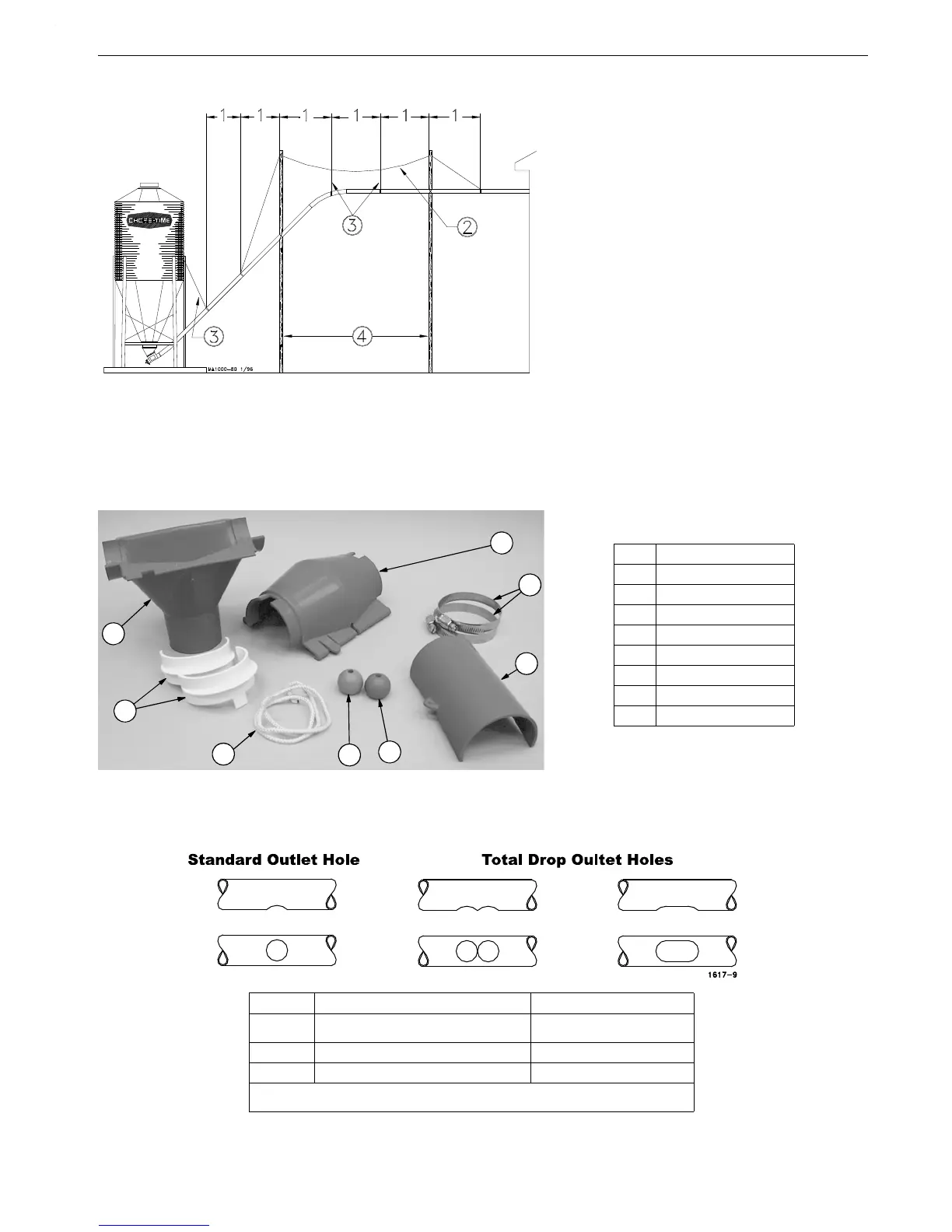
The Model 55, 75, HMC/90 Outlet Assemblies are designed to drop feed from a Feed Delivery or Feeding System
into a Gravity Drop Tube. Figure 12 shows the components that make up an outlet assembly.
1.Determine the location of the Outlet Assembly and drill or cut the desired outlet hole as shown in Figure 13.
Figure 11.Long Elevated Systems
Key Description
1 5’ (1.5 m) for PVC systems
10’ (3 m) for STEEL systems
2 Master Cable
3 Cable or Chain
4 20’ (6 m) Maximum
Figure 12.Outlet Assembly Components
Item Description
1 Outlet Bottom
2 Retainer (Optional)
3 Cord
4 Green Indicator Ball
5 Red Indicator Ball
6 Rotary Slide
7 Clamp (Optional)
8 Outlet Top
Model Standard Outlet Hole Total Drop Outlet Hole
55 1-1/2'' [38.1 mm] Dia
3'' - 5'' [76.2 - 127 mm]
*
75 2-1/2'' [63.5 mm] Dia 5'' [127 mm]
HMC/90 2-1/2'' - 3'' [63.5 - 76.2 mm] Dia 6'' [152.4 mm]
*3" for Model 55 System, 5" for Multi-flow System
Figure 13.Cutting the Outlet Hole in the Fill System Pipe