Installation Model 55,75,90, & HMC FLEX-AUGER
24
MA1702D
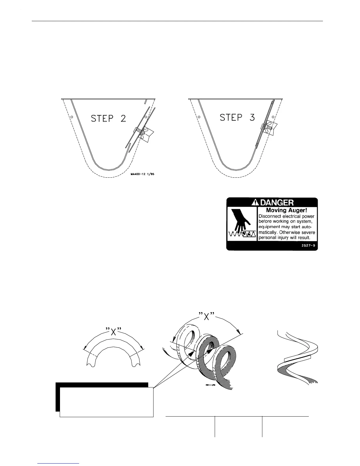
Cover Plate Installation
The cover plate is installed after installation of the auger in the tube (See Figure 24).
To install the cover plate:
1.Loosen wing nuts to end of studs
2.Start lower side of cover plate in boot opening.
3.Slide the cover plate up as far as possible so that plate catches top of boot opening.
4.Hold the cover securely while tightening the wing nuts.
Auger Brazing/Filing
If the auger needs to be spliced or lengthened, locate the brazed joint
closer to the power unit to minimize feed flow restriction in the line.
To align the auger for brazing, lay it in angle iron and clamp securely.
Rotate the auger to allow both the inside and outside edges of the augers
to be brazed.
Butt the ends of the auger against each other. DO NOT SCREW ONE
AUGER INSIDE THE OTHER--This restricts the feed flow.
Figure 25 and the associated chart specify how far to lap the augers.
A bronze, flux-coated rod is recommended. The joint should be well filled and smooth so that it does not wear
against the tube. Allow the joint to air cool.
File the auger edges, as shown in Figure 25, to avoid damage to the auger tubes. Also, file off any brazing that
extended beyond the outside radius of the auger flightings.
Figure 24.Cover Plate Installation
System
Model Model Model
55 Auger 75/HMC Auger 90 Auger
1.0 to 1.13” 1.5 to 1.75” 1.5 to 1.75”
(25 to 29 mm) (38 to 45 mm) (38 to 45 mm)
X=
Note: Sharp Auger Ends at the
to avoid damage to Auger Tube(s).
braze(s) must be filed or ground
Figure 25.Auger Brazing/Filing