Installation Model 55,75,90, & HMC FLEX-AUGER
12
MA1702D
Installation Notes
Install the equipment as specified in this manual. Failure to install as specified may cause damage to the equipment
and/or cause personal injury or death.
Take special notice of the warnings and safety decals on the equipment and in this manual.
Always wear protective clothing and protective glasses when working with the equipment.
Discarded materials, equipment, and boxes may be recycled. Recycle according to local and national codes.
Unless otherwise specified, the Model 55, 75, 90, & HMC Systems are installed similarly.
All the systems are available with straight-out or 30 degree upper boots, except the Model 55. The Model 55
requires the 30 degree upper boot (the straight-out boot is not available for the Model 55).
Bin Location and Collar Information
For easiest installation and trouble-free operation, locate the feed bin in a direct line with the FLEX-AUGER
System. The layout chart provides some points of reference for bin placement according to the height at which the
system enters the building.
The bin collar is installed during bulk bin assembly. Chore-Time bins have a welded collar. Bin Adapter Kits are
available to modify existing bins so that the welded collar can be used. In addition, most other feed bin
manufacturers have a collar available to be used with Chore-Time FLEX-AUGER Feed Delivery Systems.
Boot Installation
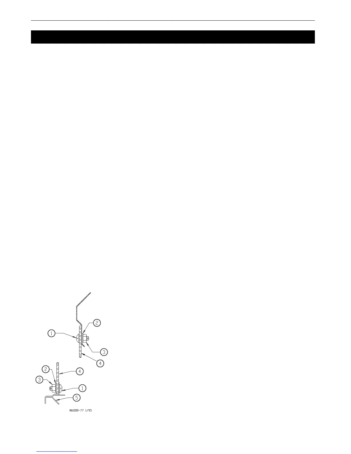
1.Insert the upper boot into the bin collar opening and turn it to line up with the direction that the auger line
will go. The boot must be as far up into the opening as it will go. Use the holes in the ring for drilling guides
and drill 11/32" (8.8 mm) holes in the upper rim of the boot. Attach the boot to the Bin Collar using the hard-
ware provided. See Figure 3. for correct use of hardware to attach the boot.
IMPORTANT: Failure to install the hardware as shown in Figure 3 may cause breakage of the
Upper boot body.
2.Attach the transfer plate to the upper boot. Use truss head bin-seal bolts installed from the inside of the plate,
with flat washers placed under the nuts.
3.Insert the slide into the transfer plate slot so that it is in its operating position before bolting the slide shield in
place. Use two 5/16-18x3/4" hex head machine screws to secure the shield.
4.Bolt the lower boot to the transfer plate using four 5/16-18x3/4" hex head machine screws.
Auger Tube Installation
Installation
Key Description
1 5/16-18x3/4" Truss Head Screw
2 5/16" Nylon Washer
3 5/16-18 Nylon Hex Nut
4 Upper Boot Body
5 Transfer Plate
6 Welded Bin Collar
Figure 3.Boot Installation Diagram