Installation Model 55,75,90, & HMC FLEX-AUGER
20
MA1702D
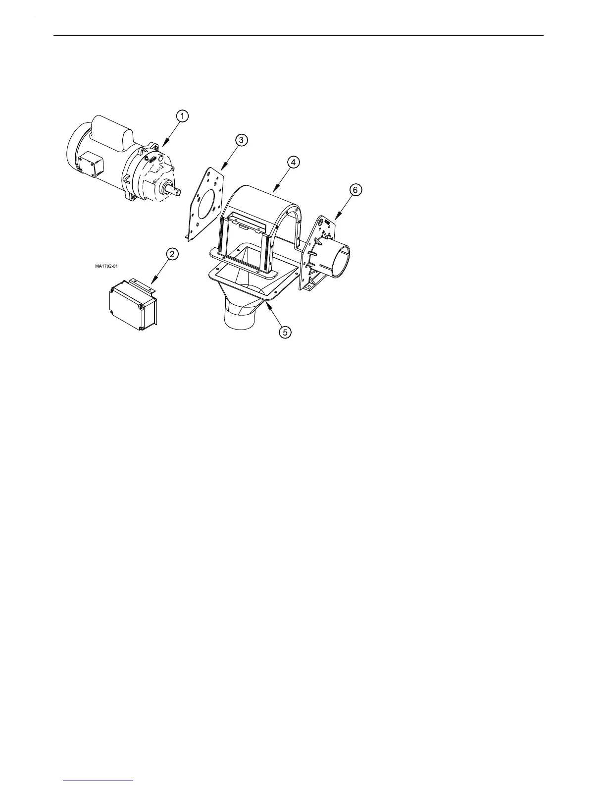
Control Unit & Power Unit Installation
1.Attach the tube anchor to the appropriate end (determine the best side of control unit for switch placement)
of the control unit body by inserting the 1/4-20x.75 carriage bolts from the inside of the control unit through
the tube anchor and attach 1/4-20 flange hex nut.
2.Connect the power unit to the gearhead end plate using the 5/16-18 machine screws and the flat washers
packed with the control.
3.Attach the gearhead end plate to the control unit body the same as the tube anchor.
4.Insert the lower section of the switch assembly into the control unit and secure the top with the 2 #10x.5
screws provided.
For Single Phase Direct Drive Control Units
1.Connect the electrical wires on the power unit to the control unit.
2.Drill bottom of control unit switch box with 7/8”(22.2mm) hole to receive the 90o connector and motor
wire. Use caution not to disturb any wires or components of the switch box ass’y when drilling holes.
3.Attach the 90 degree connector& conduit to the control unit housing.
4.Attach the insulated motor wires to the terminal block in the control housing: one wire to terminal "3"
and one wire to terminal "4". Attach the bare grounding wire to one of the green colored screws
provided for attaching the grounding wires.
5.Place the adjustable tube clamp on the tube anchor and connect the control unit/power unit assembly to the
end of the FLEX-AUGER tube.
Note:The switch in the control unit is a safety backup switch in case the hopper level switch or drop
tube switch fails to shut off the system. DO NOT use the safety switch to control the FLEX-
AUGER System. This will cause feed to bridge in the control.
Key Description
1 Power Unit
2 Switch Assembly
3 Gearhead End Plate
4 Control Body
5 Control Unit Funnel
6 Tube Anchor End
Figure 19.Control Unit/Power Unit Assembly