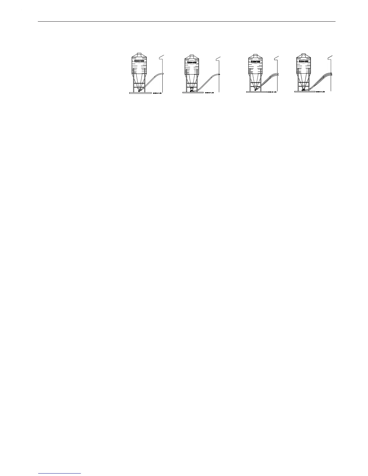
30 Degree Straight-Out 30 Degree Straight-Out
Item Description Single Boot Single Boot Twin Boot Twin Boot
--
5
Complete System 6539
5
or 6539SS
5
*
6540
5
or 6540SS
5
* 6873
5
or 6873SS
5
* 36 80 1
5
or 36801SS
5
*
--
2
Lower Boot Assembly 36442 or 36442SS* 36589/ or 36589SS* 36389 or 36389SS* 36390 or 36390SS*
1A
6
30 Degree Upper Boot 4347R
6
- - - - 4347R
6
- - - -
1B
6
Straight Out Upper Boot - - - - 6093R
6
- - - - 6093R
6
2
3
Transfer Plate Weldment 4359 4359 4359 36641
3
3
Slide 4357 or 4357SS* 4357 or 4357SS* 4357 or 4357SS* ----
4
3
Slide Shield 4876 4876 4876 14827
5
3,8
Chain Assembly 27374 27374 27374 27374
7 Neoprene Seal 2613 2613 2613 2613
8 Seal Ring 2612 2612 2612 2612
10 Cannonball 3531 3531 3531 3531
11 Single Boot Body 36588 or 36588SS* 36588 or 36588SS* - - - - - - - -
12 Twin Boot Body - - - - - - - - 36350 or 36350SS* 36350 or 36350SS*
22
4
Back Plate Weldment 6298 or 6298SS* 6298 or 6298SS* 6298 or 6298SS* 6298 or 6298SS*
23
4
Clean-Out Cover 6301 or 6301SS* 6301or 6301SS* 6301 or 6301SS* 6301 or 6301SS*
26A Tube Clamp Kit 6515 6515 6515 6515
28
1
5/16-18 x 3/8” Set Screw 1174 1174 1174 1174
29
1
5/8” Set Collar 1386 1386 1386 1386
34
1
Clamp Pin 4702 4702 4702 4702
35
1
5/16-18 x 1/2” Set Screw 5095 5095 5095 5095
36
1
Anchor Shaft 43281 43281 43281 43281
39
4
Sealing Washer 8491 or 8491SS* 8491 or 8491SS* 8491or 8491SS* 8491 or 8491SS*
40
4
5/16-18 Wing Nut 2146 or 2146SS* 2146 or 2146SS* 2146 or 2146SS* 2146 or 2146SS*
41
1
Tube Clamp Kit 4141 4141 4141 4141
42
7
2.75 x 3.0 Tube 6147 6147 6147 6147
44 Bearing Cap 35440 35440 35440 35440
45
1
Safety Cap 29702 29702 29702 29702
46
1
Anchor Tube Weldment 6840 6840 6840 6840
47 S-O/S-T Single Baffle - - - - 35731 or 35731SS* - - - - - - - -
48 30° Single Baffle 35732 or 35732SS* - - - - - - - - - - - -
49 Cannon Ball Guard - - - - - - - - 35843 or 35843SS* - - - -
50 Twin End Baffle (75) - - - - - - - - 35845 or 35845SS* - - - -
54 Twin End Baffle (75) - - - - - - - - - - - - 35845 or 35845SS*
55 Twin Outlet Baffle (75) - - - - - - - - - - - - 35846 or 35846SS*
58
3,8
Hairpin 13906 13906 13906 13906
59
8
Slide - - - - - - - - - - - - 14821 or 14821SS*
60
8
Transfer Plate Assembly - - - - - - - - - - - - 36642
61
8
Slide Shield Assembly - - - - - - - - - - - - 14827
1
These components may be ordered as a Model 75 Anchor Bearing Assembly under Chore-Time Part No. 37346 with Long
Restrictor and Chore-Time Part No. 37347 with Short Restrictor.
2
Items 2 through 55 and item 58 (as listed above) make up the Lower Boot Assemblies (Single or Twin).
3
Items 2 through 5 and item 58 may be ordered under Chore-Time Part No. 6284 or 6284SS*.
4
Items 22, 23, 39, & 40 may be ordered under Chore-Time Part No. 6197 or 6197SS* Clean-Out Cover Ass’y.
5
All Complete Systems will come with transparent Red upper boot(s) unless specified with a “C” (i.e. Complete System #
6539C) This “C” indicates the Complete System will come with transparent Clear upper boot(s).
6
Upper boot Part No.’s will have a suffix “R” for transparent Red upper boots (i.e. 4347R) or will have a suffix “C” for
transparent Clear upper boots (i.e. 4347C).
7
Stub Tube (Item 42) For Opposing Anchor.
8
Included in 36683 Twin Boot Slide Assembly.
*SS=Stainless Steel.