Model 55,75,90, & HMC FLEX-AUGER Installation
13
MA1702D
The FLEX-AUGER Delivery System includes two 45 degree elbows as standard equipment. These elbows are
used to make the sloping portion of the auger line at the feed bin, and elsewhere in the system if necessary. If
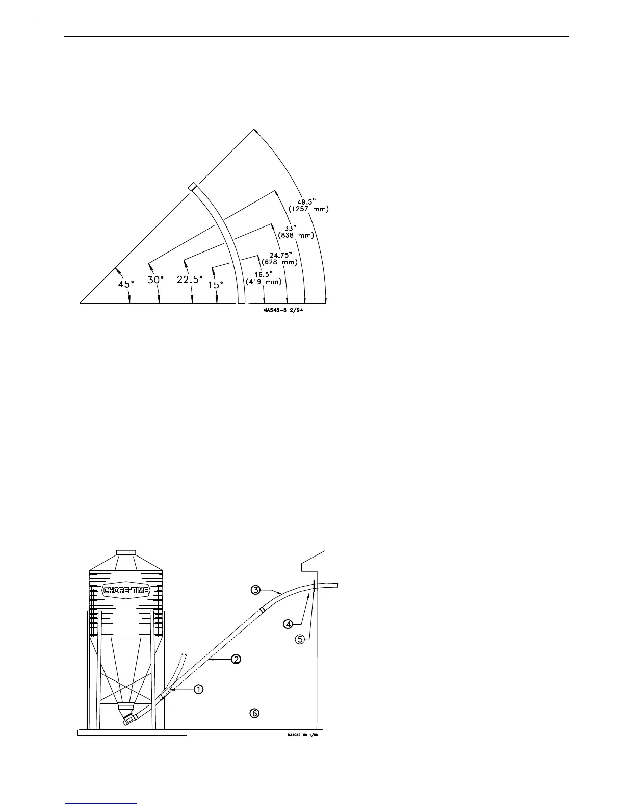
additional elbows are required, they should be ordered separately. Figure 4 shows how the elbow can be cut into
shorter sections.
1.Determine where the entrance hole for the auger tube must be located on the building and cut it.
2.Cut the elbow used where the auger enters the building (if necessary). Slide the seal ring and neoprene seal
over the straight end of the elbow and place it in the hole cut in the building, with the belled end outside the
building. (See Figure 5).
3.Model 75, 90, & HMC: Slide the belled end of the elbow or auger tube over the outlet end of the boot. A
clamp is provided to secure the elbow or auger tube to the boot.
Model 55: Install the Model 55 Stub Tube over the outlet end of the boot. A clamp is provided to secure the
Stub Tube to the boot.
Slide the belled end of the first elbow or auger tube over the stub tube.
4.Place the end of a straight section of tube inside the belled end of the elbow in the building. Hold the straight
section of auger tube so that it touches the elbow on the boot. Mark the spot where the tube aligns with the
"boot" elbow and cut the elbow at that point.
5.Place the belled end of the auger tube over the end of the elbow just cut, and hold the tube against the top
15 Degree Elbow .........16.5" or 419 mm
22.5 Degree Elbow ......24.75" or 628 mm
30 Degree Elbow .........33" or 838 mm
45 Degree Elbow .........49.5" or 1257 mm
These dimensions are measured along the
long, outside curve of the elbow. They do
not include the belled end of the elbow in
the measurement.
Figure 4.PVC Elbow Cutting Guidelines
Key Description
145° Elbow
2 Auger Tube
345° Elbow
4 Seal Ring
5 Neoprene Seal
6 Note: Belled end of elbows
and auger tubes should be
towards boot.
Figure 5.Elbow Installation outside the building