Installation Model 55,75,90, & HMC FLEX-AUGER
14
MA1702D
elbow. Mark and cut the straight auger tube so that it will fit between the two elbows. Remember to cut the
auger tube long enough to fit inside the belled end of the elbow in the building. Figure 4 shows the direction
the auger is to run in relation to the belled end of the tube. NOTE: In some installations it may be possible to
eliminate the elbow on the boot, using only a straight auger tube and one elbow where the tube enters the
building.
6.Dry-fit all parts. When satisfied that elbows and tubes fit together smoothly, glue with PVC cement
according to the following instructions.
The auger tubes and elbows for the FLEX-AUGER systems are made of specially formulated PVC tubing.
Use the PVC solvent cement to make strong, reliable bonds.
FOLLOW DIRECTIONS ON THE CAN FOR SAFE HANDLING OF CEMENT.
1.Be sure tube is cut off squarely. Remove burrs from outside and inside the end of the tube.
2.Dry fit all parts. Tube should fit inside belled end of next tube to full depth without excess force.
3.Clean surfaces to be joined. SURFACES MUST BE FREE OF DIRT OR GREASE!
4.Apply a generous coat of cement to both the inside of the belled end and outside of the other tube. Be
sure cement covers all of the joint area so there are no bare spots.
5.Quickly join the tubes, giving them a twisting motion to bring them into alignment as they are joined.
6.Keep pressure on the joint until the PVC cement sets up.
ALL TUBE JOINTS EXPOSED TO MOISTURE AND WEATHER MUST BE SEALED OR
CAULKED TO WATERPROOF THEM IN ADDITION TO CEMENTING OR CLAMPING THE
JOINT!
7.If there is more than 15 feet (4.5 meters) of auger tube between the boot and the building, provide
additional support for the tubes so that the boot does not have to carry the weight of the auger. Extra
support can be achieved with cables or chains fastened to the bin legs and auger tube.
8.Install the remaining tubes in the system AFTER the outlet holes have been located and cut. The auger
tubes should be cemented using PVC cement supplied. NOTE: The tubes can be joined by cutting off
the belled ends and fastening tubes together with tube connectors if there is some reason why
permanent installation is not desired. (Tube Connectors are not standard equipment and must be
ordered separately for this type of installation).
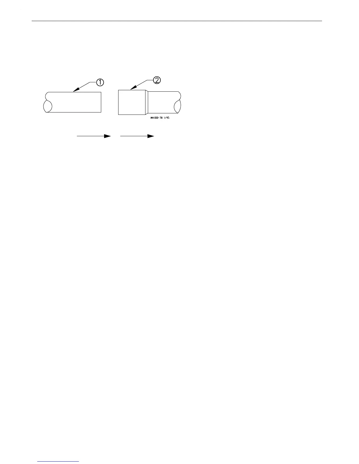
Direction of Travel
Key Description
1 Straight section of Auger
Tube
2 Belled end of Auger Tube
Figure 6.Proper Auger Tube Connection