Model 55,75,90, & HMC FLEX-AUGER Installation
23
MA1702D
4.Assemble the control unit funnel to the tube anchor and the gearhead end plate with 4 1/4-20x.63 hex head
bolts and1/4-20 hex flange nuts. The straight side of the funnel should be position on the power unit side of
the control.
5.Pull on the loose end of the auger at the boot once or twice until it begins to stretch, then release it slowly.
This will bring the auger to its natural length.
IMPORTANT: On Single Boot Systems, Stretch the auger 2 inches (50 mm) for every 50 feet (15.2
m) of length. Example: For a 150 ft. (45 m) system the auger should be cut 6 inches
(150 mm) shorter than its natural length. Measure the amount of stretch from the
rear edge of the boot and cut the auger at that point.
Note: For ease of cutting, measure and mark the auger at the point where it is to be cut. Then, pull
the auger an additional 6-8" (150-200 mm) and use locking pliers to clamp the auger while you
cut it.
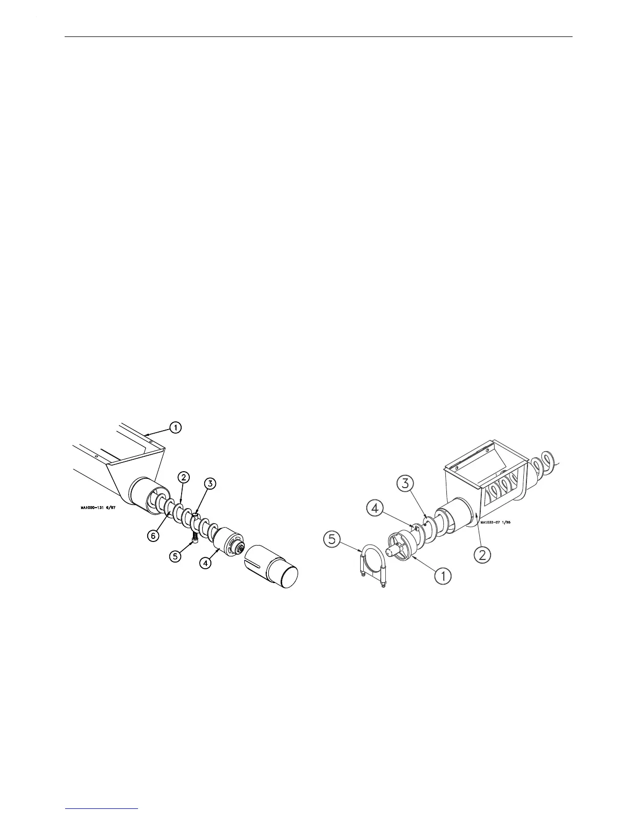
6.Figure 23 shows the proper assembly of the Model 55 boot components. Insert the Auger over the Anchor
and through the Auger Clamp until Auger touches washer. Torque Set Screw into Auger Clamp 10-12 ft.-lbs.
Over tightening the Set Screw may cause damage to the Auger Clamp.
Figure 23 shows the proper assembly of the Model 75, 90, & HMC anchor components. Insert the anchor
into the auger until the auger touches the anchor flange. The auger must be threaded onto the Boot Anchor
Assembly, through the clamp pin. Use a 5/16” open-end wrench to tighten the clamp pin setscrew on the
auger.
Some of the Boot Models have Anchor and Bearing Assemblies with Restrictors that may be
shortened, if necessary, to increase capacity.
7.Attach the anchor assembly to the boot.
8.Place the cannonball in the boot.
Key Description
1 Anchor and Bearing Assembly
2 Lower Boot
3 Auger
4 Tighten Set Screw to secure Auger
in Clamp Pin
5 Tube Clamp
Figure 23.Anchor and Bearing Installation
Model 90 & HMC Models
Key Description
1 Model 55 Lower Boot
2 Model 55 Auger
3 Auger Clamp
4 Anchor Bearing
5 Tighten socket screw to
secure auger to the Anchor.
6 Anchor
Model 55