Installing the Suspension System MODEL C2® PLUS & MODEL G™ PLUS with Proximity Sensor Feeding System
12
MF2495A
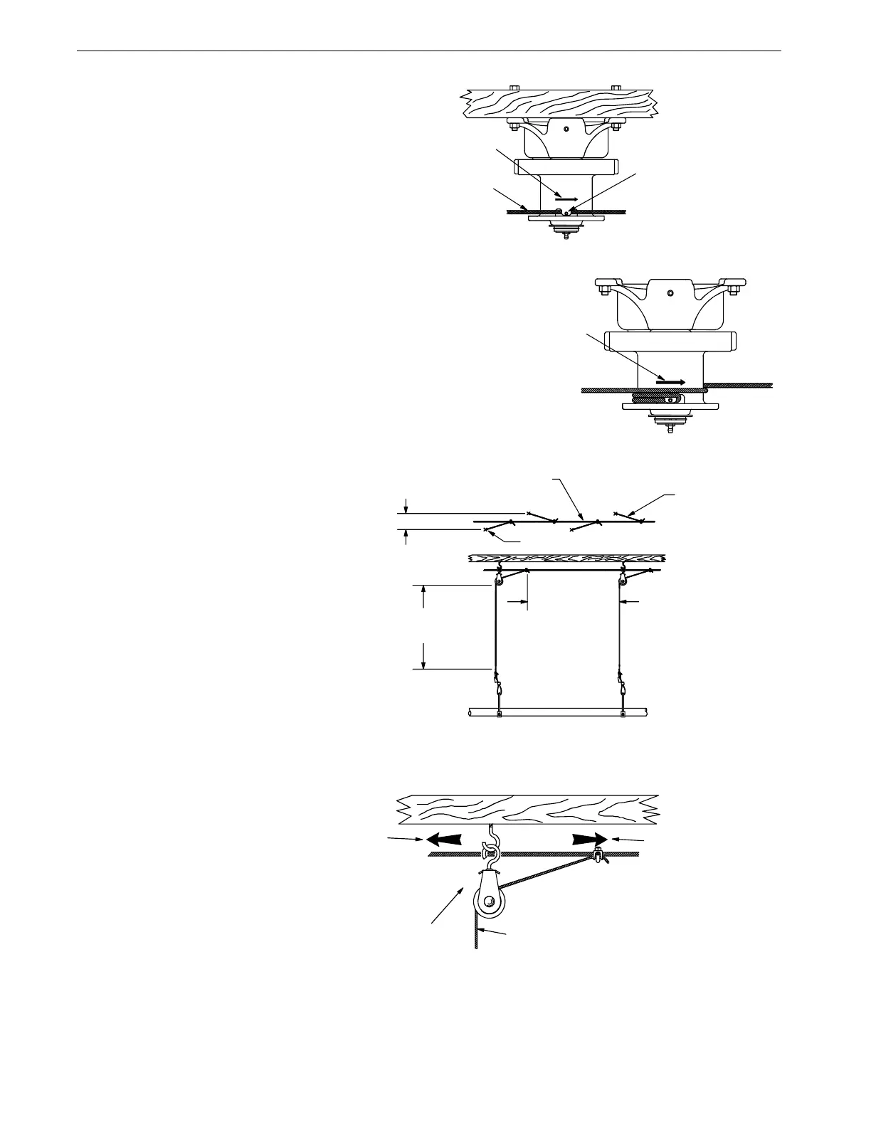
4.Route the cable through the Winch Drum
Relief located near the bottom of the
drum. Tighten the set screw to anchor the
cable to the drum. See Figure 11.
5.Turn the winch drum one full revolution.
Guide the cable against the flange at the bottom of the
winch drum. The cable must not wrap over itself on the
drum, but should be wrapped as close as possible to
each previous wrap. See Figure 12.
Screw Hook Installation
The recommended distance between the
drops for the feeder line is 8’ [2.4 m] on
center. Do not exceed 10’ [3 m] spacing on
drop lines.
If the distance raised is greater than the
distance between the drop spacings, offset
the hooks 3" [7.6 cm] to each side of the
line to prevent the cable clamps from
catching the pulleys, see figure 13.
Screw the hook into the truss
the full length of the threads to
prevent bending.
The openings of the screw
hooks must be pointed away
from the direction of travel
when the Power Winch raises
the feeder line. See Figure 14.
1255-80 1/2001
1) Winch Drum Relief
with Set Screw
2) 3/16" Main
Winch Cable
3) Drum Direction
of Rotation
Figure 11. Attaching the Cable to the Power Winch
1255-81 9/2000
1) Drum Direction
of Rotation
Figure 12. Power Winch Drum Rotation
1255-70 1/2001
1) 3/16" [5 mm]
Main Winch Cable
3) Screw Hook or Ceiling Hook Location
2) 3/32" [2 mm]
Drop Cable
4) Distance
of Cable
Travel
5) Distance Feeder
is to be Raised
6) 3" [7.6 cm]
Offset
Figure 13. Drop Line Off Set Detail
1) Screw Hook
opening facing
opposite direction
of travel
2) Winch End
(Direction of Travel)
3) 3/16" Main
Winch Cable
4) 3/32" Drop Cable
1255-73 1/2001
Figure 14. Screw Hook Installation