Hopper Assembly Procedure MODEL C2® PLUS & MODEL G™ PLUS with Proximity Sensor Feeding System
14
MF2495A
The 150 lb. Hopper Assembly is NOT designed for single-point suspension. The upper cross brace is designed
for supporting the drop tube ONLY
. This Hopper Assembly is to have Two-point suspension as stated.
Assembly
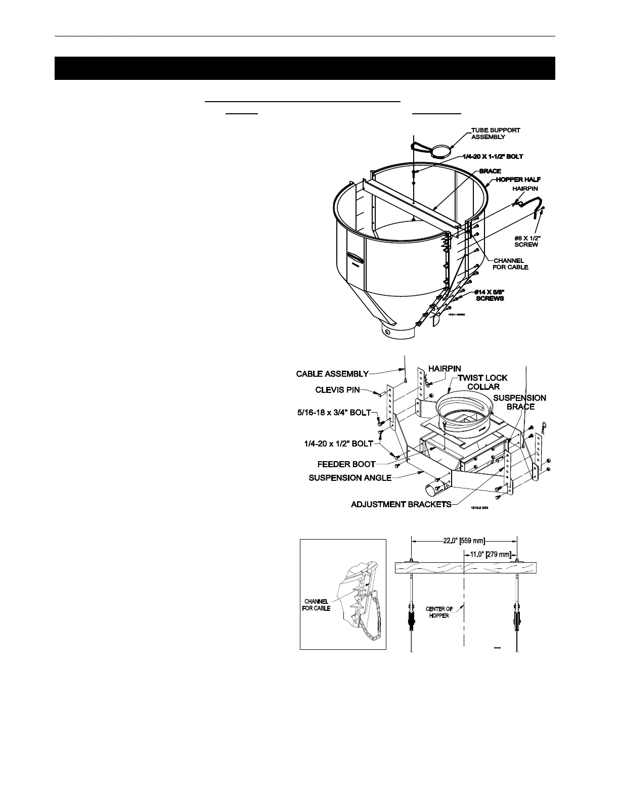
1.Assemble the 1/4-20 x 1-1/2” bolt to the brace with two
1/4-20 nuts. One nut should be assembled under the
brace with the other on top. This bolt is to provide a
place for the tube support assembly chain to be hooked,
see figure 18.
2.Assemble the 150 lb. hopper halves and brace as shown
in Figure 18, using #14 x 5/8” screws (supplied in
hardware package).
3.Assemble the #8 x 1/2” screws and chain as shown in
Figure 18.
4.Assemble suspension angles and suspension braces
around feeder line boot (single or twin), using 1/4-20 x
1/2” Hex bolts and nuts (supplied in hardware package),
see figure 19.
Note: The larger holes on the ends of the suspension
angles need to be on the upper side of the
assembly.
5.Assemble the twist lock collar to the top of the
feeder line boot (single or twin) using 1/4-20 x
1/2” bolts and lock nuts (supplied in hardware
package), see figure 19.
6.Assemble the adjustment brackets to the
suspension angles with 5/16-18 x 3/4" bolts and
nuts (supplied in hardware package).
7.Two cable assemblies (cable with a sleeve clamp
and a 5/32 thimble) are supplied with the
suspension kit to support the hopper. Attach the
cable assemblies to the adjustment brackets
using the top holes of the adjustment brackets,
see figure 19.
8.Install two pulleys to either a 2" x 8"
[50x200 mm] board that will span at least 3
rafters or a 3/8” [9.5 mm] thick steel plate
welded to two pieces of angle iron that are
long enough to span at least 2 rafters. Install
the pulleys directly above the feeder line
where the hopper is to be located. The
pulleys should be spaced 22" [559mm]
apart (11" [279 mm] from the center of the
hopper in both directions), see figure 20.
Suspend the Hopper
1.Attach the boot to the feeder line.
2.Route the two cable assemblies up and around the pulleys.
3.Level the boot with the feed line and clamp the cables to the main cable using 1 cable clamp per cable
assembly.
4.Place the hopper on top of the twist lock collar and rotate the hopper 90 degrees into position.
Make sure the cables lay in the channels on the sides of the hopper for support then use the hairpin
to contain the cable.
Hopper Assembly Procedure