MODEL C2® PLUS & MODEL G™ PLUS with Proximity Sensor Feeding System Management
MF2495A
39
This section provides you with valuable information concerning feeder operation and management. It is important
that you read this information and understand how the feeding system was designed to operate. Once you become
familiar with the system, you may custom operate it to fit your individual needs.
Initial Start-up of the Feeding System
The Feeding System should be operated prior to birds being housed to make sure the installation is correct, the
switches function properly, and to fill the feeder lines with feed.
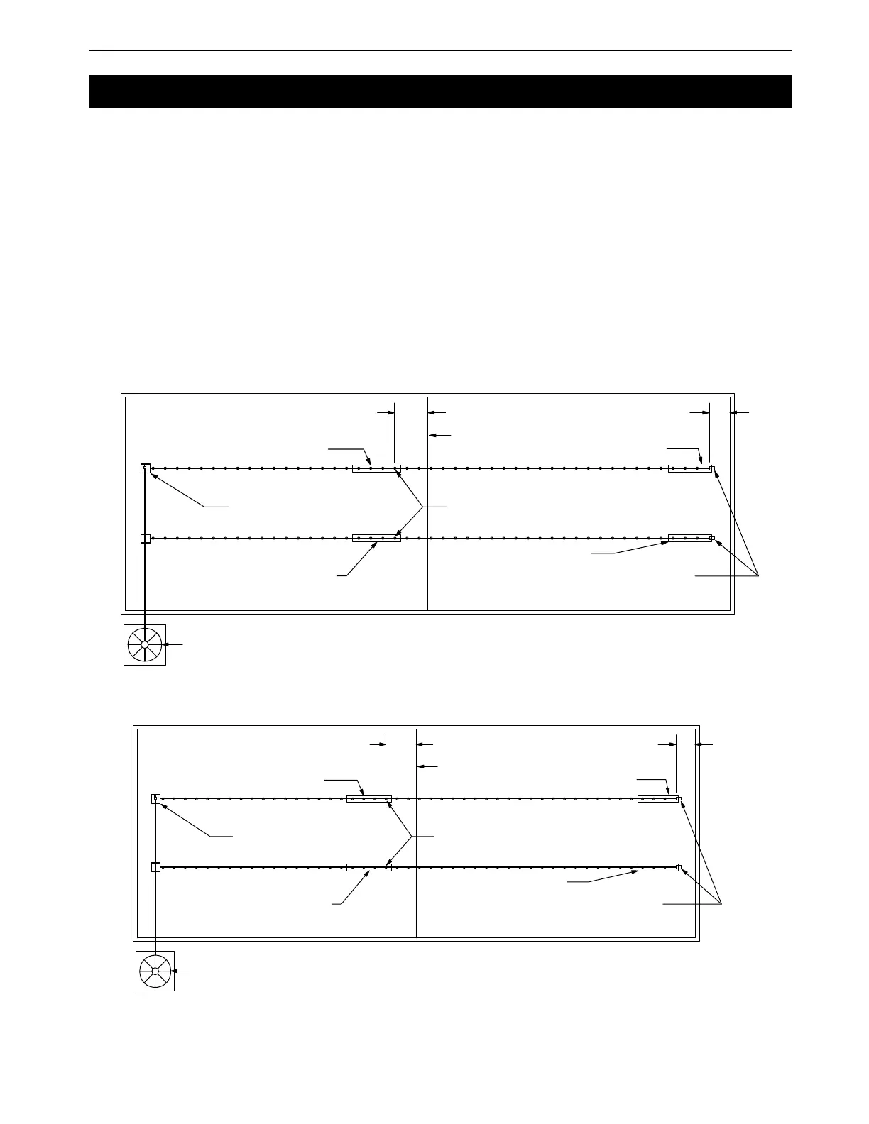
There are two typical layouts for the feeding system that was determined prior to the installation. Normally if the
building is 400’ [122 m] or over, a center house hopper set-up is used. See Figure 61. For buildings under 400’
[122 m], the hopper is placed at one end and the control pan/power unit at the other end. See Figure 62.
It is common practice to use partial house brooding during the early days of broiler production. For buildings that
have the feeder split in the center (center hopper set-up), normally only the feeders that are in the brood area are
used during brood time. For buildings that have the hopper at one end, brooding can be done on the motor end or
an optional mid line control pan(s) can be placed on the feeder line.
Figure 61.Component location diagram for systems over 400 feet [122 m]. (Top View).
Management
1255-68 1/2001
Feed Bin
Feed Hopper
Mid Line Control
Brood Curtain
End Control
& Power Unit
Control Tube
Control Tube
Control Tube
Control Tube
10' [3 m]
Minimum
10' [3 m]
Minimum
1255-68 1/2001
Feed Bin
Feed Hopper
Mid Line Control
Brood Curtain
End Control
& Power Unit
Control Tube
Control Tube
Control Tube
Control Tube
10' [3 m]
Minimum
10' [3 m]
Minimum
Figure 62.Component location diagram for systems up to 400 feet [122 m]. (Top View).