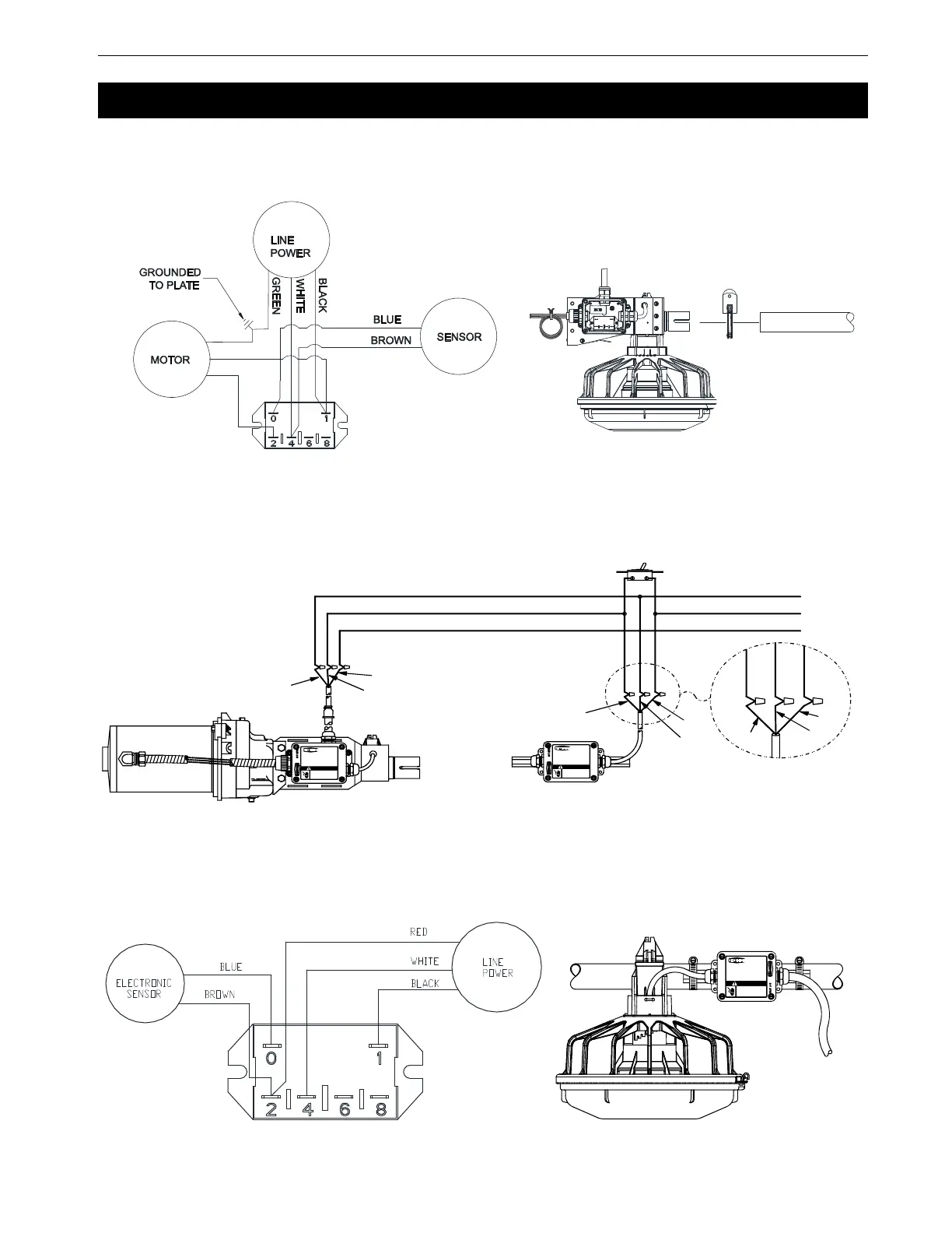
MODEL C2® PLUS & MODEL G™ PLUS with Proximity Sensor Feeding System Wiring
MF2495A
31
End Control with Electronic Sensor Internal Wiring
Electronic Sensor Control Wiring Diagram
Mid Control with Electronic Sensor Internal Wiring
Wiring
End Control with Electronic Sensor
End
Control
L1
L2
Ground
3 Wire Hook Up (Typical)
Ground
L1
L2
1255-106 10/2000
2529-710
42680 MODEL C2 PLUS
END CON TROL
WITH PROXIMITY SWITCH
CHORE-TIME EQUIPMENT
A DIVISION OF CTB INC .
MILFORD, INDIANA 46542-2000
Do not open this control
box until electrical power is
disconnected at circuit breakers.
ELECTROCUTION HAZARD!
DANGER
2529-711
42663 MODEL C2 PLUS
INTERMEDIATE CONTROL
WITH PROXIMITY SWITCH
CHORE-TIME EQUIPM ENT
A DIVISION OF CTB IN C.
MILFORD, INDIANA 46542-2000
Do not open this control
box until electrical power is
disconnected at circuit breakers.
ELECTROCUTION HAZARD!
DANGER
Intermediate
Control
Shown with
3259-84
Power Unit
Bypass Switch
(not supplied)
230 VAC
Supply
60 HZ
Green
Black
White
Red
Black
White
White
Black
Red
1255-66 6/01
2529-711
42663 MODEL C2 PLUS
INTERMEDIATE CONTROL
WITH PROXIMITY SWITCH
CHORE-TIME EQUIPMENT
A DIVISION OF CT B INC.
MILFORD, INDIANA 46542-2000
Do n ot open this c ontro l
box until electrical power is
disconnected at circuit breakers.
ELECTROCUTION HAZARD!
DANGER
Mid Control with Electronic Sensor