Installing the End Control, Boot Assembly, and Auger MODEL C2® PLUS & MODEL G™ PLUS with Proximity Sensor Feeding System
20
MF2495A
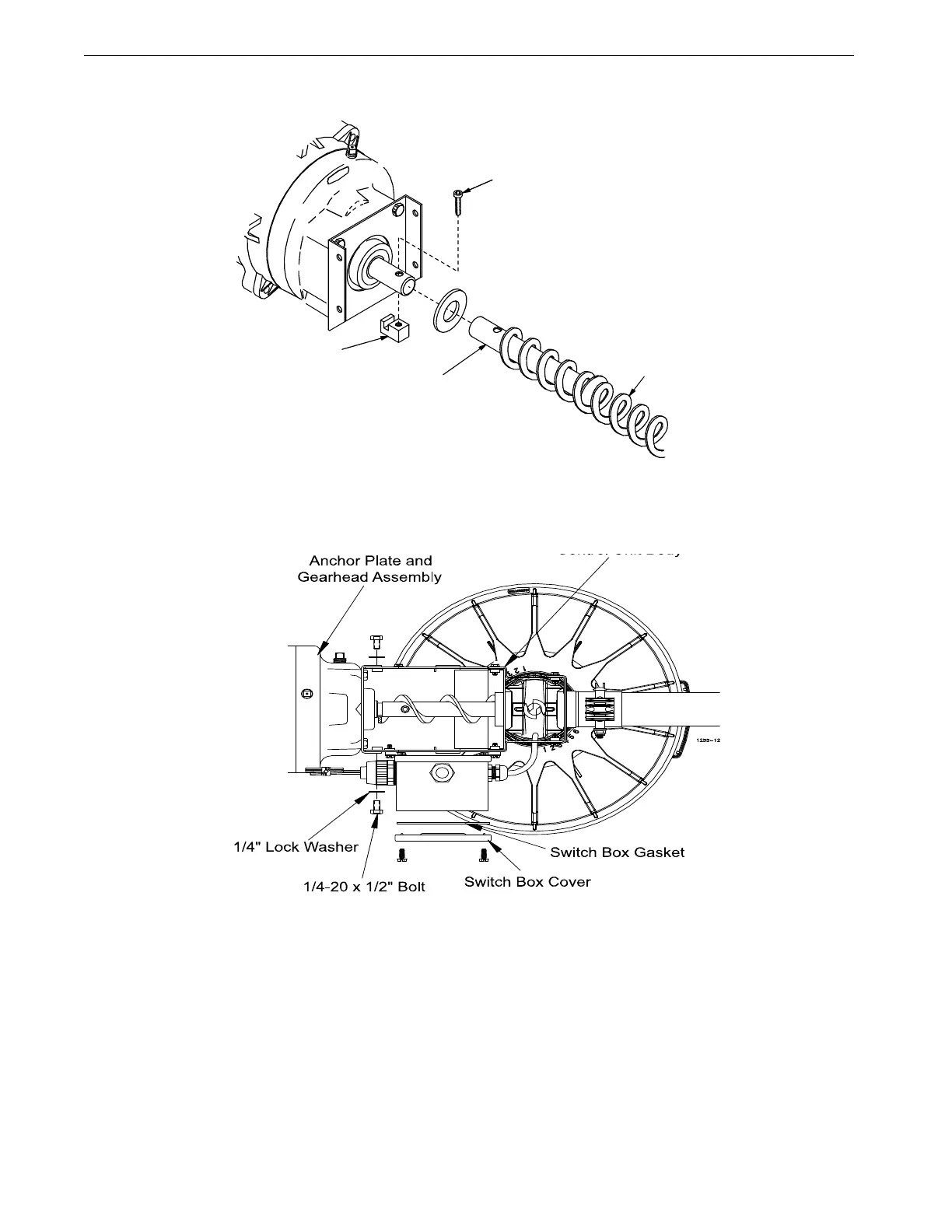
Figure 32. Use the Driver Block to secure the auger to the Output Shaft.
7.Attach the Anchor Plate and Gearhead Assembly to the Control Unit Body using the included 1/4'' Lock
Washers and 1/4-20 x 1/2'' Bolts. See Figure 33.
8.Install the Metal Water Tight Connector (Item 1) in the Feed Line Motor (Item 2). Cut the Flex Conduit
(Item 3) to length. Slide the wires from the end control through the Flex Conduit (Item 3). Install the Flex
1255-93 4/2001
2) Drive Tube Weldment
1) Driver Block
3) Control Unit not
shown for clarity
4) 1/4-20 x 1-1/2"
Socket Head Bolt
6) Auger
Figure 32.Auger Driver Components
Figure 33. Attaching the Anchor Plate and Gearhead Assembly
to the Control Unit Body