Auger Installation MODEL C2® PLUS & MODEL G™ PLUS with Proximity Sensor Feeding System
24
MF2495A
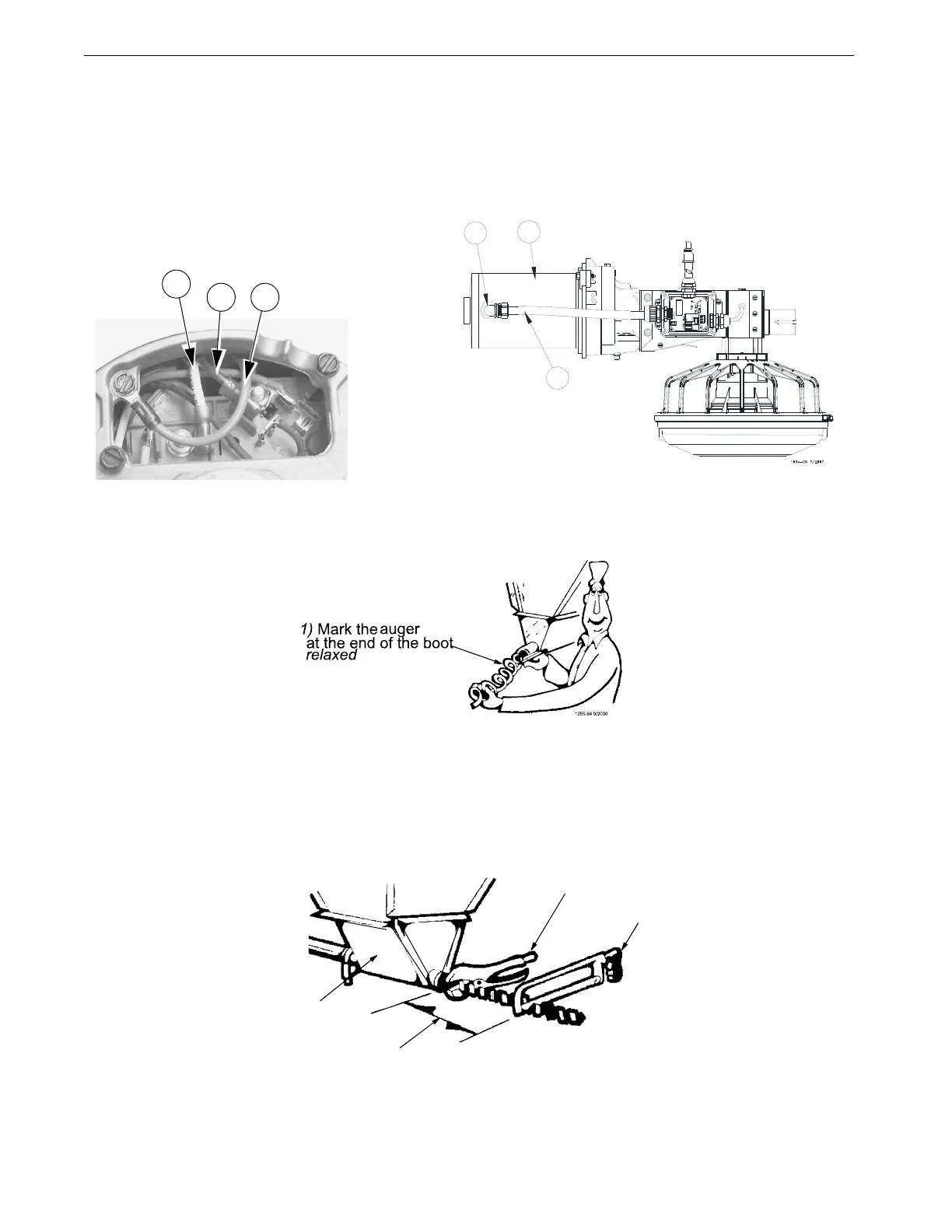
8.Install the Metal Water Tight Connector (item 1) in the Feed Line Motor (item 2). Cut the Flex Conduit
(item 3) to length. Slide the wires from the end control through the Flex Conduit (item 3). Install the Flex
Conduit (item 3) in the connectors. Connect the wires to the Feed Line Motor (item 2), see figure 40.
9.Attach all covers and wire according to the wiring section of this manual.
10.Pull the auger at the boot end until it begins stretching. Then let it relax. In the relaxed position, mark the
auger at the end of the boot. See Figure 41.
11.Auger stretch:
The auger needs to be stretched 7" [180 mm] per 100’ [30 m]. Example: A 300’ [90 m] feeder line requires
21" [500 mm] of stretch.
Beginning at the relaxed position, measure the required amount of stretch. Mark the auger at that point.
Grip the auger 8" [200 mm] ahead of this mark with locking pliers. Allow the auger to pull back into the boot
so that the pliers rest against the end of the boot. See Figure 42.
Use a hacksaw or bolt cutters to cut the auger at the stretched auger mark.
End Control
1
2
3
Figure 40.Wiring the Motor
Motor Wiring
4
5 6
Figure 41.Measure the Auger from relaxed
1255-95 9/2000
1) Locking Pliers
2) Use a hacksaw or bolt
cutters to cut the auger
3) Pull an extra 8" [200 mm] of auger (minimum)
to allow for Anchor and Bearing Installation
4) Boot under Feed Hopper
Figure 42. Cut the Auger with required stretch