MODEL C2® PLUS & MODEL G™ PLUS with Proximity Sensor Feeding System Mid-Line Control
MF2495A
27
Mid-Line Control will be installed.
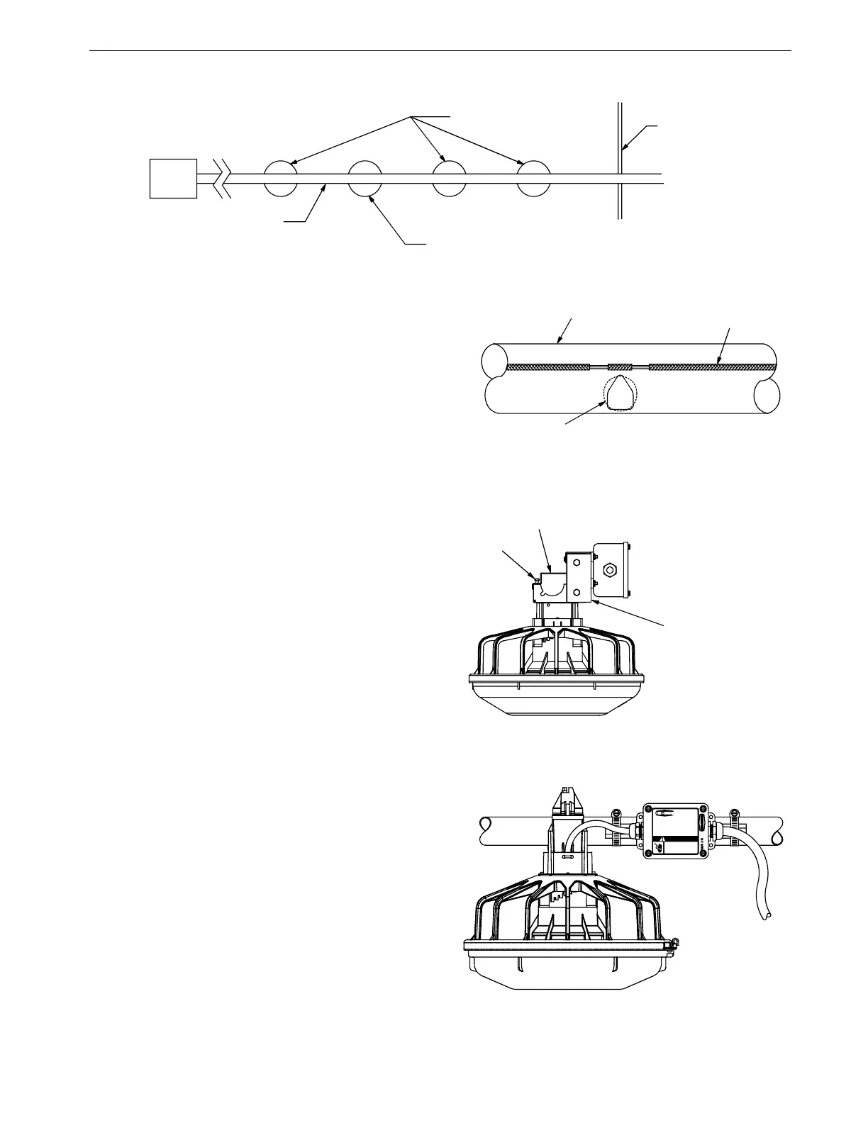
Figure 46.Mid-Line Control Location Diagram
2. New Feeder Lines: Go to step 3.
Existing Feeder Lines: Enlarge the outlet hole to
approximately 1'' [2.5 cm] diameter for the
Mid-Line Control, plus enlarge (2) outlet holes in
front (to the hopper end) of the Mid-Line Control.
Use unibit to enlarge hole size. Be sure there are no
burrs inside the tube to catch the auger.
3. Install the Mid-Line Control:
Mechanical Switch:
a. Remove the two hex head screws on
the control top.
b. Lift off the control top.
c. Cradle the feeder tube in the control
housing. The feeder tube may have
to be turned slightly to allow the pan
to hang straight.
d. Clamp the control in place by
inserting tabs on the control top into
the slots on the control body. Install
and tighten the two hex head screws
previously removed.
Electronic Sensor:
a. Assemble the Mid-Line Control to the Feeder
Tube as shown in Figure 49.
b. Attach the Switch Box Assembly to the Feeder
Tube with Hose Clamps as shown in Figure 49.
4. Install a toggle switch, out of reach of the birds,
to disconnect power to the Mid-Line Control.
This allows the Mid-Line Control to serve as
standard feeder when not used as a control
feeder.
5. Wire the Mid-Line Control as shown in the
wiring diagram section of this manual.
1255-99 4/2001
1) Hopper at end
of the feeder line
5) Mid Line Control
2) Feeder Pan
3) Brood Curtain
4) Control Tube
(new installations)
1255-100 9/2000
1) Auger Tube
2) Seam
3) Use a Unibit to enlarge outlet holes
on existing feeder lines
Figure 47.Enlarging Outlet Holes
1255-101 9/2000
1) Mid Line Control
3) Control Top
2) Hex Head Scew
Figure 48.Mid-Line Control Installation
1255-66 6/01
2529-711
42663 MODEL C2 PLUS
INTERMEDIATE CONTROL
WITH PROXIMI TY SWITCH
CHORE-TIME EQUIPMENT
A DIVISION OF CTB INC.
MILFORD, INDIANA 46542-2000
Do not open th is control
box until electrical power is
disconnected at circuit breakers.
ELECTROCUTION HAZARD!
DANGER
Figure 49. Installing the Mid Line Control