ULTRAFLO
®
Cage Feeding Systems for Brood Grow & Layer Installations Installation for Layer Cage Systems Only
15
MC656P
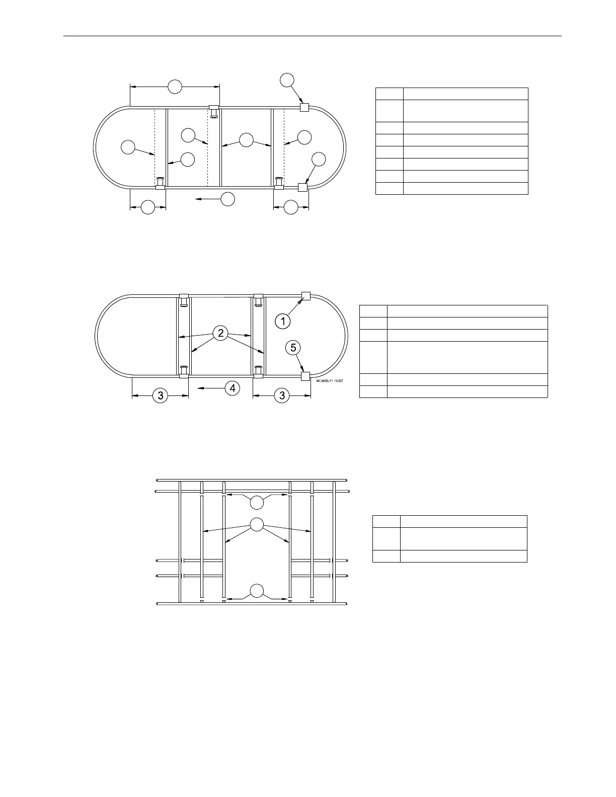
Three Power Unit System
Four Power Unit System
If cages are to be removed to allow space for Power Units, cut the cage front wires shown in Figure
18. to allow room for the Power Unit to be installed.
5
2
1
5
3
4
4
3
3
6
7
MC656-22 10\97
Key Description
1 Locate the Power Unit in the
center of the cage row.
2 Intake Cup
3 Motor Support Stand
4 Cage Floor Support
5 64' (19.5 m)
6 Auger Direction
7 Clean Out (typical location)
Figure 16.Power Unit Location Diagram for Three Power Unit Systems (top view)
Key Description
1 Intake Cup
2 Cage Floor Stand or Motor Support Stand
3 Systems up to 500' (152 m): 80' (24 m)
Systems over 500' (152 m): 120' (37 m)
Systems over 600' (198 m): 152' (46 m)
4 Auger Direction
5 Clean-Out (typical location)
Figure 17.Power Unit Location Diagram for Four Power Unit Systems (top view)
MC656-14 8/95
Key Description
1 Cut out these cage front wires to
allow for motor installation.
2 Cut here.
Figure 18.Modify cage for Power Unit Installation (front view).
 Loading...
