ULTRAFLO
®
Cage Feeding Systems for Brood Grow & Layer Installations Installation for Layer Cage Systems Only
25
MC656P
End Components Installation
Intake Cup Installation
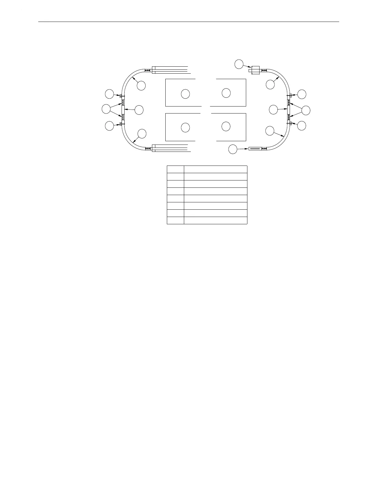
1.Install the Intake Cup on the right hand side of the cage row, as shown in Figure 34 Remem-
ber.
a.The top of the Intake Cup must be level.
b. The flat side of the Intake Cup must be toward the aisle.
2.Use Clamp to secure the elbow to the Intake Cup.
Intake Cover Installation—Covers Included.
Self-tapping sheet metal screws are supplied to fasten the Covers on the Intake Cups.
Clean-Out Section Installation
1.Install the Clean-Out Section on the return side of the cage row. It may be installed at either
end of the cage row or between elbows.
The opening in the Clean-Out Tube must be facing down.
2.Use a Clamp to secure the Elbow to the Clean-Out Section, as shown in Figure 34.
3.To operate, turn the Clean-Out Cover down to allow feed to drop out. Turn Clean-Out Cover
up to prevent feed drop out.
NOTE: NEVER RUN FEEDER WITH CLEAN-OUT COVER REMOVED.
MC656-78 10/97
2
1
2
3
6
6
6
6
3
2
2
4
5
4
7
4
5
4
Key Description
1 Intake Cup
2 Elbow
3 Straight Section of Tubing
4 Elbow Brace
5 Clamps
6 Cage Row
7 Clean-Out Assembly
Figure 34.Trough Installation at Power Unit Location (front view)
 Loading...
