Planning the Installation ULTRAFLO
®
Cage Feeding Systems for Brood Grow & Layer Installations
6
MC656P
• Careful planning is required to insure an easy installation and proper operation of the equipment.
• Prior to beginning the installation, read the installation instructions that apply to your equipment.
This will save time and help avoid confusion.
Important: Due to the complexity of the equipment, make certain you are installing it properly as you
go.
Note: Different cage systems require different installation procedures for installing Power
Units, Troughs, and some Hangers. Be careful to refer to the appropriate section when
installing this equipment. The rest of the installation instructions for the different cage
systems are the same, except where noted.
Power Unit Requirements
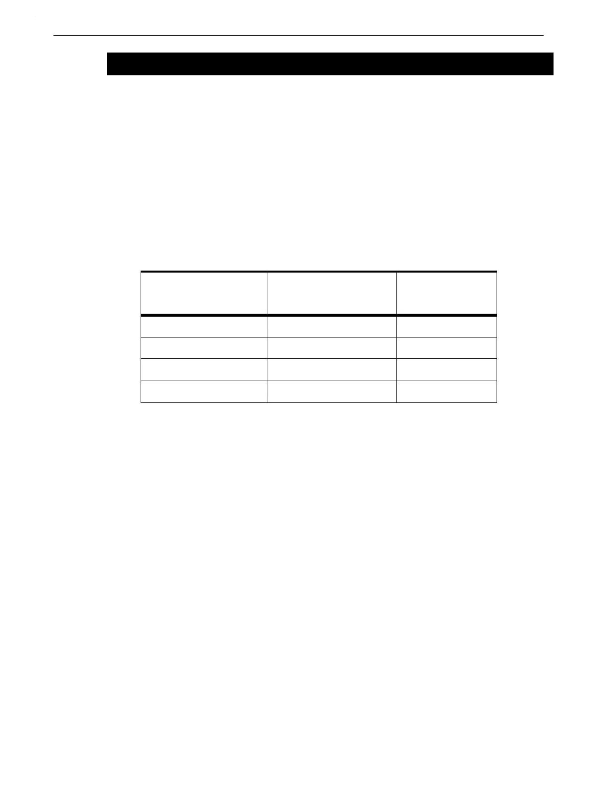
Use the chart below to determine the required number of Power Units for each ULTRAFLO
®
loop in
your installation. The chart applies to layer and brood-grow cage styles.
Note: 208 volt power will require a 20% reduction in line length recommendations.
Hanger Requirements
Refer to the ULTRAFLO
®
Hanger Chart on page 10 to help determine which Hangers are required
for your installation. The ULTRAFLO
®
Hanger Chart also specifies the distance between Hangers.
Additional Manuals
Refer to the following manuals as required for related equipment installation instructions.
• Model 55, 75, 90, & HMC FLEX-AUGER Fill System Manual MA1000
• Model 108 FLEX-AUGER Fill System Manual MA1032
• Model 90, 108, & Dual 90 Feed Screener Manual MC1033
• Feeder and Fill System Maintenance Schedule MC821
• ULTRAFLO
®
Loop Fill System Manual MC1191
• Dead End Fill System Manual MC1190
• 3 & 4 Output Control Instructions MC832
Note: Some of the instructions listed above are available in various languages. Contact your
CHORE-TIME Distributor for additional manuals.
Planning the Installation
Cage Row Length
for 60 Hz. Systems
(230 volts at Power Units)
Cage Row Length
for 50 Hz. Systems
(230 volts at Power Units)
Number of Power
Units Required
Up to 120' (36 m) Up to 96' (29 m) 1
121' (37 m) to 448' (137 m) 97' (30 m) to 358' (109 m) 2
449' (137 m) to 505' (154 m) 359' (109 m) to 404' (123 m) 3
over 505'(154 m) 404' (123 m) to 600' (183 m) 4
 Loading...
