ULTRAFLO
®
Cage Feeding Systems for Brood Grow & Layer Installations Installation for Brood-Grow Cage Systems Only
11
MC656P
Trough
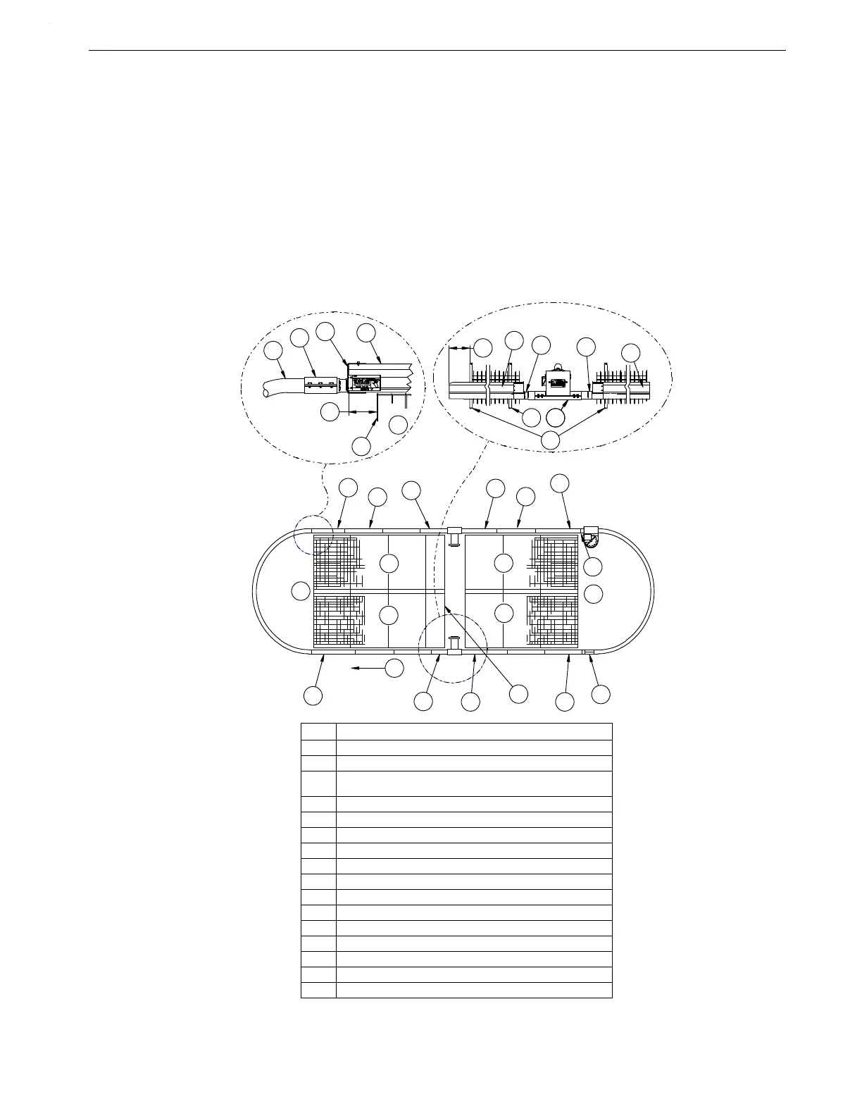
Note: It is very important that the Trough installation be started correctly. When properly
installed, the trough joint will be approximately 8" (20 cm) to the right of the Floor Support.
Refer to Figure 8. when determining trough starting locations, Power Unit-to-Trough
connections, etc.
• Always work from left to right when installing trough.
Trough Sections are shipped in ten foot (3 m) lengths. Four special 11' (3.35 m) Starter Trough
Sections are shipped with each line to be used where needed for proper trough alignment. See
Figures 8 through 13 for Trough Installation.
Various Hangers are used to hold the Trough in place. Refer to Figure 9, 10, or 11 (depending on
your cage style) for identification and correct installation of Hangers.
Key Description
1 Standard Trough
2 Standard Trough: Cut off expanded end as required.
3 10' Cage Sections: Use 11' Starter Trough.
8' Cage Sections: Use 9' Starter Trough.
4 Start here.
5Cage Row End
6Cage Row
7 Auger Direction
8 Motor Support Stand
9Clean Out
10 4" (100 mm)
11 Elbow
12 Tube Clamp
13 End Cap
14 Hangers may be installed here on 16" cages.
15 Power Unit Base Connector
16 Mainframe
5
6
2
13
12
11
10
3
16
14
14
2
10
8
4
5
6
6
6
6
5
3
2
3
8
9
2
2
1
2
3
7
1
3
2
3
7
15
1
MC656-81 11/97
Figure 8. Power Unit and Elbow Installation Diagram (top view)
 Loading...
