Installation for Brood-Grow Cage Systems Only ULTRAFLO
®
Cage Feeding Systems for Brood Grow & Layer Installations
8
MC656P
Power Unit Location
Determine where the power units should be located. See Figures 1 Through Figure 4 to determine
Power Unit placement.
One and three Motor Systems: A Motor Support Floor Stand should have been installed at each Power
Unit location during the installation of the cages. See Figure 1 and Figure 3. If the Motor Support Stand
is not present, install it according to the instructions packed with the Motor Support Floor Stand.
Two and four Motor Systems: A Space equal to one vertical row of cages should have been left at each
motor location for motor installation. If cages were installed, it will be necessary to remove one set of
cages and install a second main frame a minimum of one (1) cage width 24" – 30" (610 – 760 mm) from
the existing mainframe. See Figure 2 andFigure 4. Refer to instruction MD785 for additional
installation information.
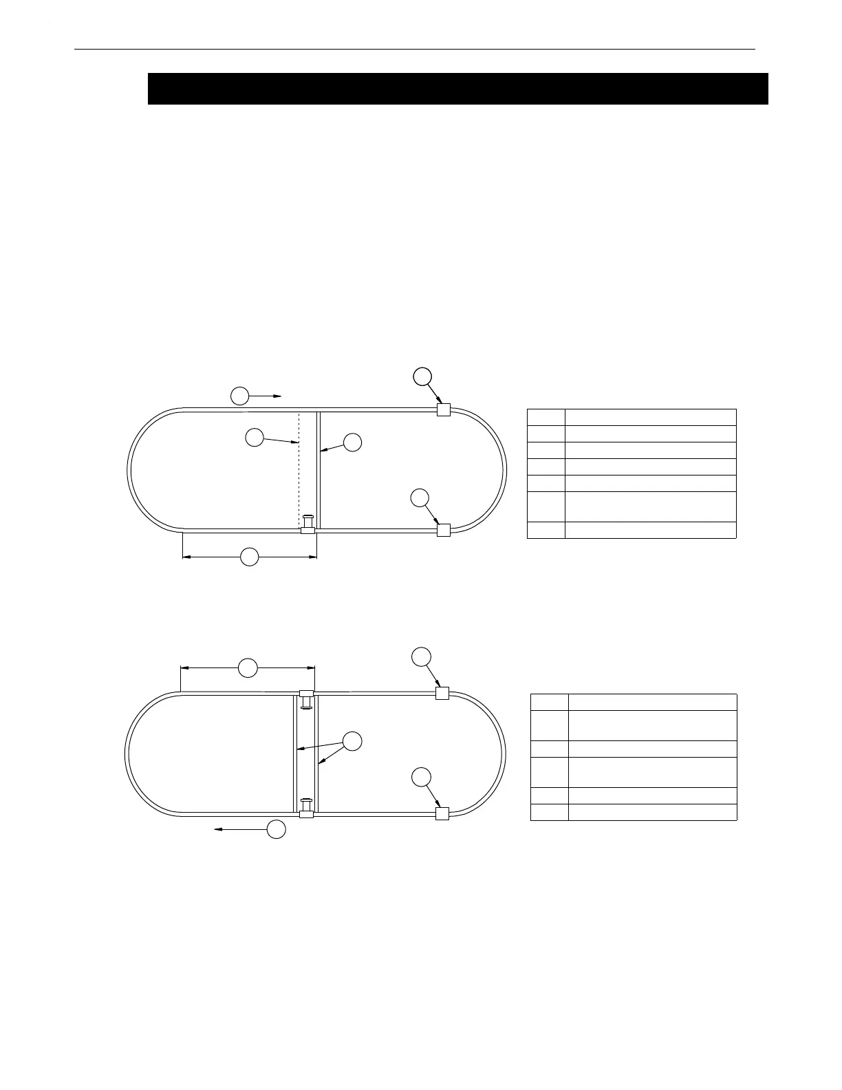
Single Power Unit System
Two Power Unit System
Installation for Brood-Grow Cage Systems Only
Key Description
1 Auger Direction
2 Intake Cup
3 Cage Floor Support
4 Motor Support Stand
5 Locate the Power Unit in the
center of the cage row.
6 Clean-Out (typical location)
Figure 1. Power Unit Location Diagram for Single Power Unit Systems (top view)
Key Description
1 Locate the Power Unit in the
center of the cage row.
2 Intake Cup
3 Cage Floor Support or Motor
Support
4 Auger Direction
5 Clean-Out (typical location)
Figure 2. Power Unit Location Diagram for two Power Unit Systems (top view)
 Loading...
