ULTRAFLO
®
Cage Feeding Systems for Brood Grow & Layer Installations Installation for Brood-Grow Cage Systems Only
9
MC656P
Three Power Unit System
Four Power Unit Assembly
If cages are to be removed to allow space for Power Units, cut the Grill, Cage Front,
and Feed Trough Shield from the front of the cage next to a Cage Floor Support
where the Power Unit is to be located. Remove the Top Fronts from this cage also
(See Figure 5.).
5
2
1
5
3
4
4
3
3
6
7
MC656-22 10\97
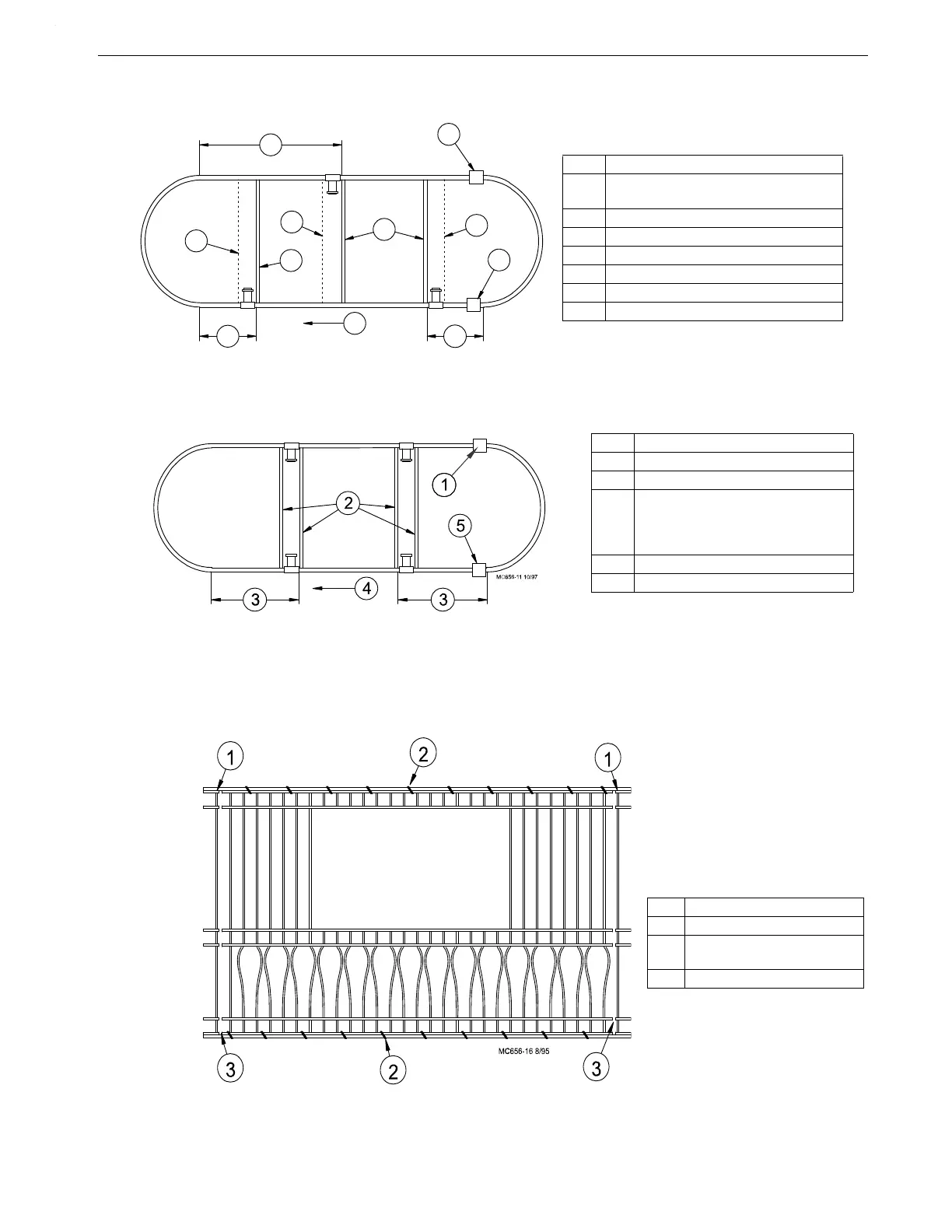
Key Description
1 Locate the Power Unit in the center of
the cage row.
2 Intake Cup
3 Motor Support Stand
4 Cage Floor Support
5 64’ (19.5 m)
6 Auger Direction
7 Clean-Out (typical location)
Figure 3. Power Unit Location Diagram for three Power Unit Systems (top view)
Key Description
1 Intake Cup
2 Cage Floor Stand or Motor Support
3 Systems up to:
500’ (152 m): 80’ (24 m)
500’- 600' (152-183 m): 120’ (37 m)
over 600’ (183 m): 152’ (46 m)
4 Auger Direction
5Clean-Out (typical location)
Figure 4. Power Unit Location Diagram for Four Power Unit Systems (top view)
Key Description
1 Partition
2 Remove the Rings along
the top and bottom
3 Cut wires along the Partition
Figure 5. Modify cage for Power Unit
 Loading...
