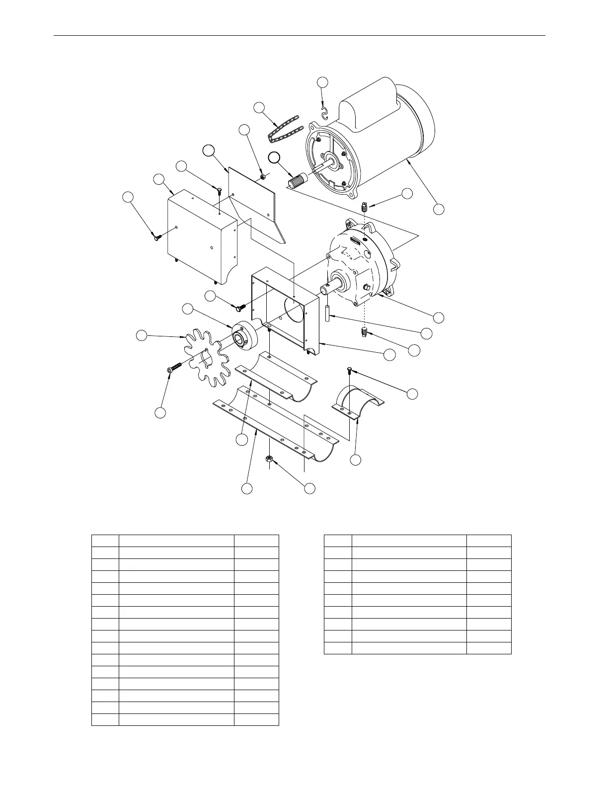
Key Description Part No.
1 Pinion Assembly See Chart
2 10-24 Stamped Nut 1560
3 Auger Brace 24674
4 10-24 Hex Head Screw 4416-3
5 Gearhead Assembly See Chart
6 Vent Plug 3523
7 Magnetic Pipe Plug 30160
8 Drive Unit Base 8207
9 #10x1/2" Self-Drilling Screw 3037
10 Drive Unit Cover 8208
11 5/16-18x3/4 Hex Head Screw 2046
12 Drive Gear Hub 8213
13 MULTIFLO Drive Gear 54383
14 5/16-18x7/8 Cap Screw 6850-1
15 Base Connector Weldment 9636
Key Description Part No.
16 1/4-20 Locknut 1269
17 Dowel Pin 8699
18 Wear Shoe 8210
19 1/4-20x1/2" Hex Head Screw 1487
20 End Connector Weldment 9634
21 Motor See Chart
22* S-Hook 723
23* Chain 1302
-- Danger Decal 2527-9
* Not included in the Power Unit/Driver
Assembly
** Gearhead & Driver Assembly Part Numbers
include items #2 through#20.
 Loading...
