ULTRAFLO
®
Cage Feeding Systems for Brood Grow & Layer Installations Installation for Brood-Grow Cage Systems Only
13
MC656P
Trough Installation (continued)
1. Fasten an End Cap to the end of one of the special 11' (3.35 m) Starter Trough Sections with
self-drilling screws. Begin w/self taper at bulb and work upward
(See Figure 12.).
2. Position the End Cap so that it sticks out 4" (100 mm) past the end of the Cage Row.
(See Figure 12.)
3. Secure the Trough Section to the cages with the Hangers. See Figures 9 Through Figure 11
4. Overlap the straight end of the next Trough Section about 1/4 inch (6 mm) over the expanded
end of the installed Trough. Snap it down into the installed Trough and then slide them together
(See Figure 13.). Fasten the Troughs together with self-drilling screws at the first two joints at
each end of the Cage Row.
5. Continue installing Trough Sections until a location for a Power Unit is reached. Then cut off
a ten foot (3 m) Trough Section as shown in Figure 8. For Power unit installation see “Power
Unit Installation” on page 23 of this manual.
6. After installing the Power Unit, continue installing Trough Sections until another Power Unit
location or the end of the Cage Row is reached.
7. At the end of the Cage Row, cut the Trough so that it sticks out past the end of the Cage Row
4" (100 mm).
8. Slide the End Cap over the cut end of the Trough and fasten with self drilling screws
(See Figure 12.).
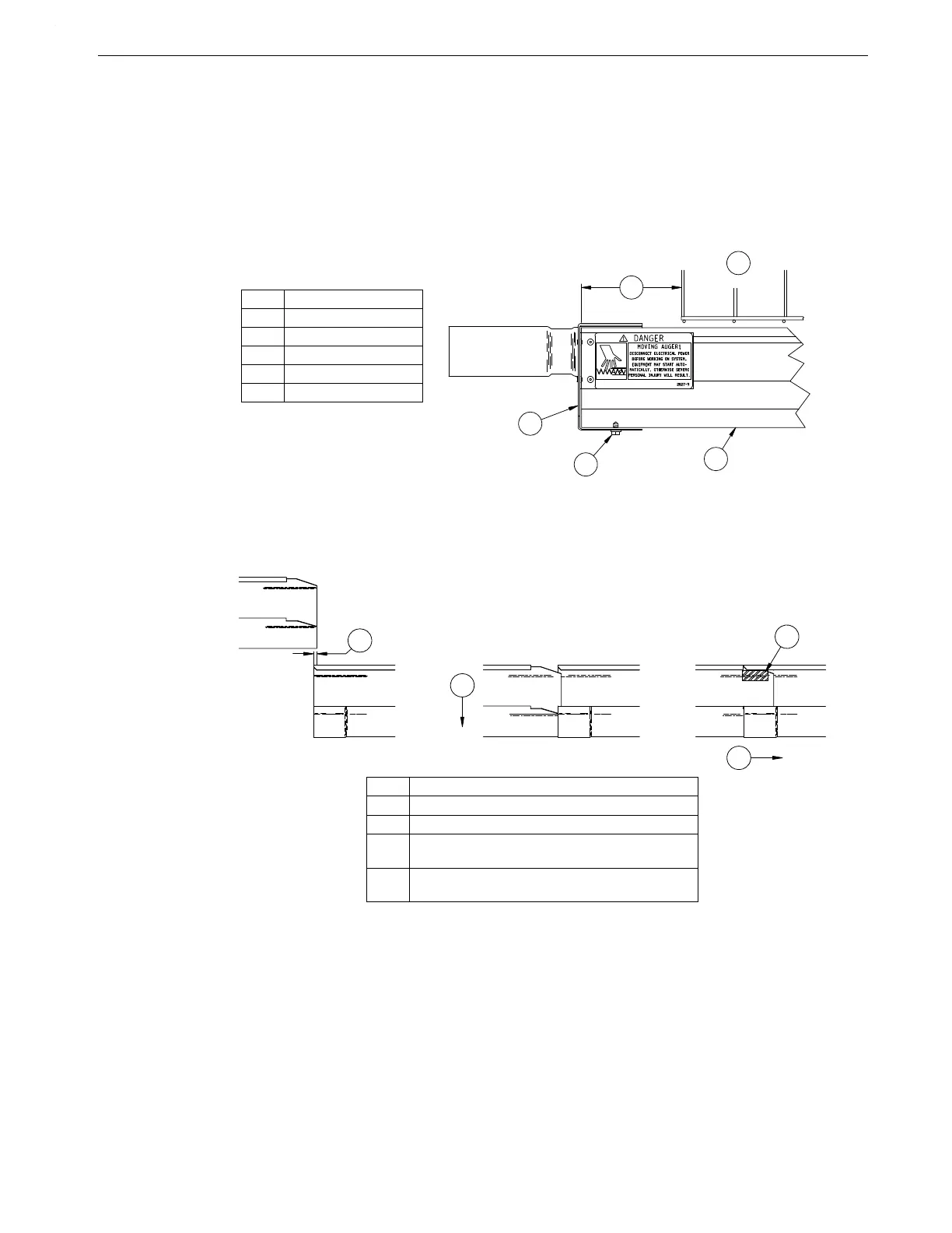
Key Description
1 4" (100 mm)
2Cages
3 Trough
4 End Cap
5 Self-Drilling Screw
Figure 12.End Cap Installation (top view).
Key Description
1 1/4" (6 mm) Gap
2Snap Down
3 Slide straight end of Trough into belled end of
the next Trough.
4 A self-drilling screw should be installed in this
area on the first two trough joints from both ends.
Figure 13.Trough Connection Diagram (side view).
 Loading...
