Operation
4-21
Figure 4-32 GO/NG Upper & Lower Comparison Rule
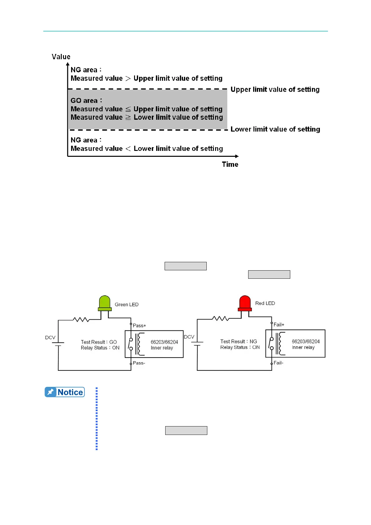
The test results are output from the PASS/FAIL indicator on the front panel and 4 PASS/FAIL
pins on the rear panel I/O port respectively. The PASS indicator is on if the test results of all
channels are PASS. If any of the test results is FAIL, the FAIL indicator will be on. The 4
PASS/ FAIL pins on the I/O port map to the test results of channel 1 ~ 4 to on the relay of
PASS or FAIL. The user can utilize the external indicators to present the PASS or FAIL
state via the figure shown below.
When the test result is FAIL, no matter it is the indicator on the front panel or the external I/O
port, all of them will blink and beep. The FAIL value will be logged on the panel for check.
If the previous test result is FAIL, press TRIG/ENTER once to clear the test result and twice
to conduct the next test. If the previous test result is PASS, press TRIG/ENTER to conduct
the next test immediately.
Figure 4-33 Wiring of GO/NG External Indicator
1. There are total 16 test parameters including V, Vpk+, Vpk-, I, Ipk+,
Ipk-, Is, W, PF, VA, VAR, CFi, VTHD, ATHD, E and F.
2. The upper and lower limits of every test parameter are different. If
the upper and lower limits are set to “- - - - -”, it means no setting.
3. The 66203/66204 Digital Power Meter has 3 parameters that
require pressing TRIG/ENTER for triggering. They are E (energy),
Is (Inrush current) and GO/NG. If two of them are set for testing,
the triggering priority is E > Is > GO/NG.