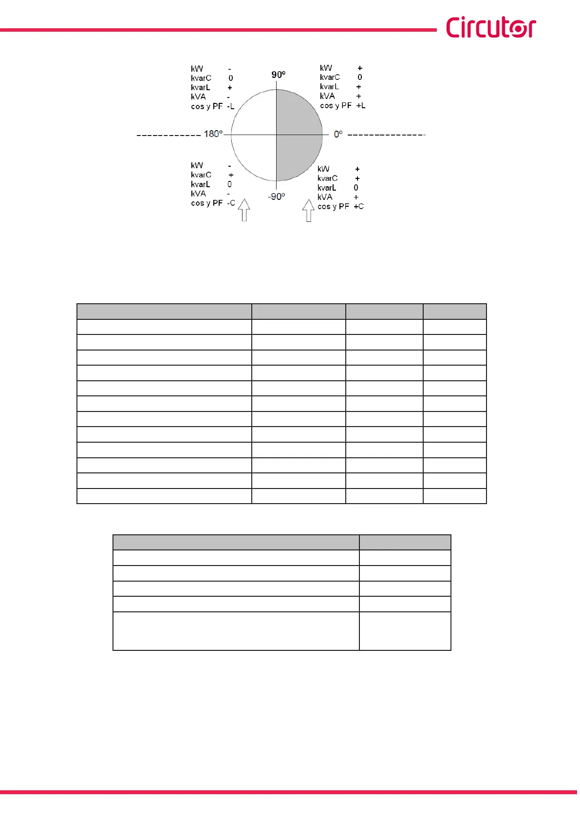
Inductive Inductive
Capacitive Capacitive
Inductive
Inductive
Capacitive Capacitive
Generated
Power
Consumed
Power
Consumed
Power
Generated
Power
Figure 20: Diagram of the four measurement and compensation quadrants.
Table 14:Modbus memory map: measurement variables (Table 2)
Parameter Instantaneous Maximum Units
L1 Fundamental Voltage Harmonic 400-401 484-485 V/100
L1 Voltage Harmonics 402-415 486-499 % / 1 0
L2 Fundamental Voltage Harmonic 416-417 49A-49B V/100
L2 Voltage Harmonics 418-42B 49C-4AF % / 1 0
L3 Fundamental Voltage Harmonic 42C-42D 4B0-4B1 V/100
L3 Voltage Harmonics 42E-441 4B2-4C5 % / 1 0
L1 Fundamental Current Harmonic 442-443 4C6-4C7 mA
L1 Current Harmonics 444-457 4C8-4DB % / 1 0
L2 Fundamental Current Harmonic 458-459 4DC-4DD mA
L2 Current Harmonics 45A-46D 4DE-4F1 % / 1 0
L3 Fundamental Current Harmonic 46E-46F 4F2-4F3 mA
L3 Current Harmonics 470-483 4F4-507 % / 1 0
Table 15:Modbus memory map: measurement variables (Table 3)
Parameter Instantaneous
Relay variable 600
Alarm variable 605-606
Status of the outputs 610
Status of the digital inputs 615
No. of connections, of each of the 14 relays
(6 in the Computer SMART III 6 model,
12 in the Computer SMART III 12 model,)
625-63E
63
Instruction Manual
Computer SMART III