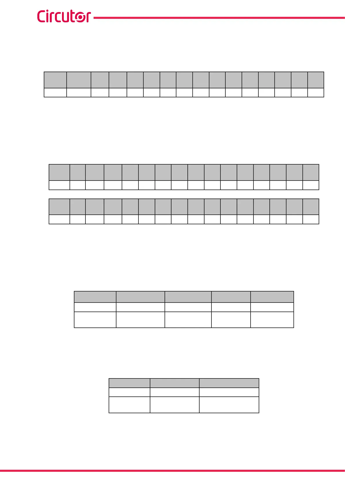
Relay variable
Shows the status of the 14 (Computer SMART III 14 model), 12 (Computer SMART III 12 model) or 6
(Computer SMART III 6 model) output relays.
It is a 16-bit variable in which each bit indicates the status of a relay.
Bit
15-14
Bit
13
Bit
12
Bit
11
Bit
10
Bit
9
Bit
8
Bit
7
Bit
6
Bit
5
Bit
4
Bit
3
Bit
2
Bit
1
Bit
0
Relay - 14 13 12 11 10 9 8 7 6 5 4 3 2 1
Where 0: relay disconnected (OFF).
1: relay connected (ON).
Alarm Variable
Shows the status of the 17 possible alarms.
It is a 32-bit variable in which each bit indicates the status of an alarm.
Bit
15
Bit
14
Bit
13
Bit
12
Bit
11
Bit
10
Bit
9
Bit
8
Bit
7
Bit
6
Bit
5
Bit
4
Bit
3
Bit
2
Bit
1
Bit
0
E16 E15 E14 E13 E12 E11 E10 E09 E08 E07 E06 E05 E04 E03 E02 E01
Bit
32
Bit
31
Bit
30
Bit
29
Bit
28
Bit
27
Bit
26
Bit
25
Bit
24
Bit
23
Bit
22
Bit
21
Bit
20
Bit
19
Bit
18
Bit
16
- - - - - - - - - - - - - - - E17
Where 0: alarm off (OFF).
1: alarm active (ON).
Status of the outputs
Shows the status of the 4 outputs: Fan relay, alarm relay and the two digital outputs.
It is a 16-bit variable in which each bit indicates the status of an output.
Bit 15 to 4 Bit 3 Bit 2 Bit 1 Bit 0
- Digital output 2 Digital output 1 Alarm relay Fan relay
- 1: OFF
0: ON
1: OFF
0: ON
1: ON
0: OFF
1: ON
0: OFF
Status of the digital inputs
Shows the status of the 2 digital inputs.
It is a 16-bit variable in which each bit indicates the status of an input.
Bit 15 to 2 Bit 1 Bit 0
- Digital input 2 Digital input 1
- 1: ON
0: OFF
1: ON
0: OFF
64
Computer SMART III
Instruction Manual