Thepowerandvoltagemeasuringcircuitmustbeconnectedwithcablesthathaveaminimum
cross-sectionof1mm
2
�
Thesecondarylineofthecurrenttransformerwillhaveaminimumcross-sectionof2�5mm
2
�
Thetemperatureratingofinsulationofwiresconnectedtothedevicewillbeatminimum62ºC�
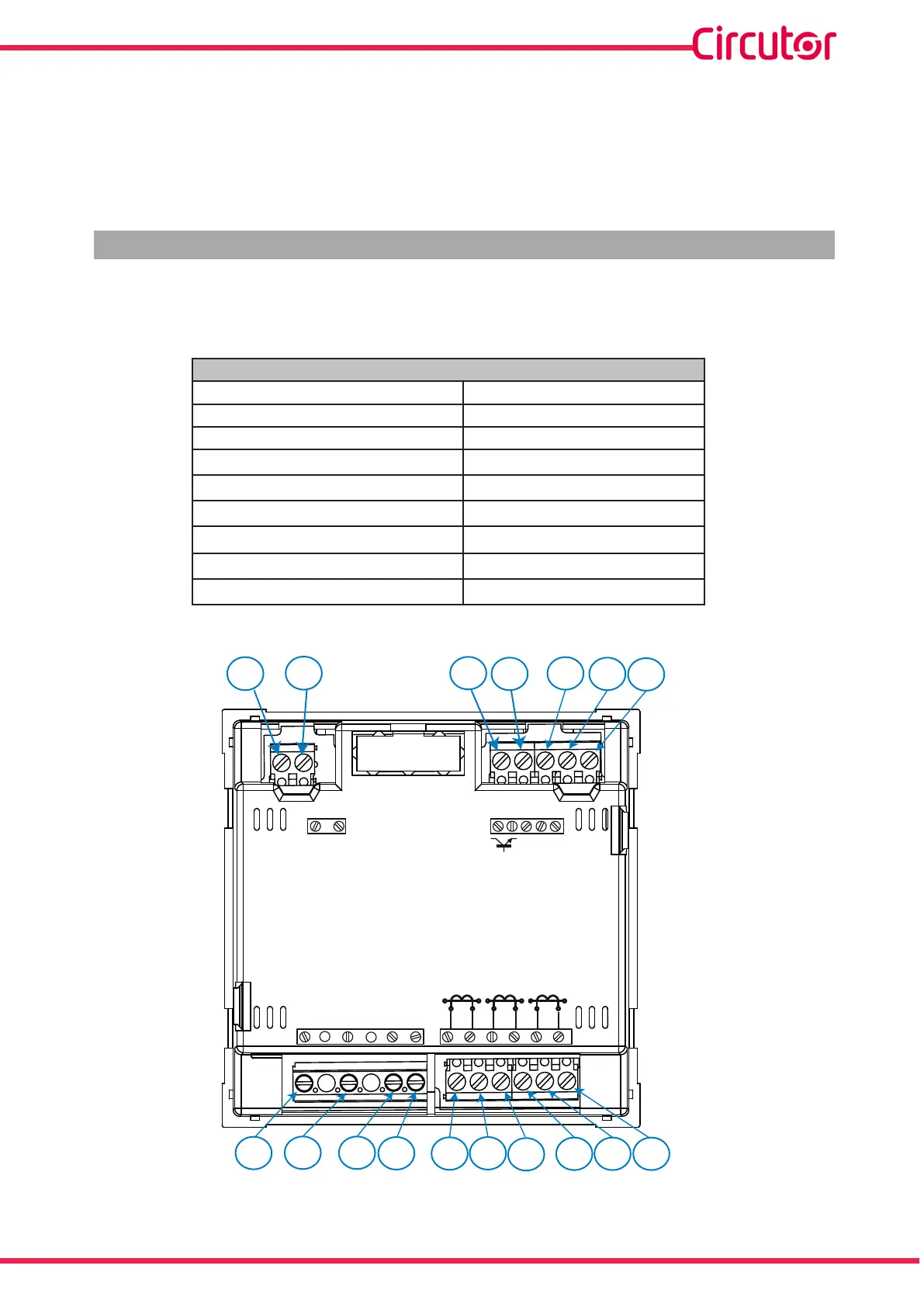
3�3�-UNITTERMINALS
3�3�1�- MODEL CVM-C5-xxx-485-C
Table 2:List of CVM-C5-xxx-485-C terminals�
Device terminals
1 :AuxiliaryPowerSupply 10: V
L3
, L3voltageinput
2:AuxiliaryPowerSupply 11: N, neutral
3: SO+,Transistoroutput 12: S
1
,L1currentinput
4: SO-, Transistoroutput 13: S
2
, L1currentinput
5: A(+),RS485 14: S
2
, L1currentinput
6: B(-),RS485 15: S
2
, L2currentinput
7: GND,forRS485 16: S
1
, L3currentinput
8: V
L1
, L1voltageinput 17: S
2
, L3currentinput
9: V
L2
, L2voltageinput
1
2
3
4
5
6 7
8
9 10 11 12 13
14
15
16 17
POWER SUPPLY
RS485
S0+ S0-
OUTPUT
S1 S2 S1 S2 S1 S2
L1
P1 P2
L2 L3
300V ~
Ph-NPh-Ph
520V
~
NV
L3L2
V
L1
V
P1 P2 P1 P2
A
(+)
B
(-)
GND
Figure 1: CVM-C5-xxx-485-C terminals�
9
Instruction Manual
CVM-C5-xxx-485