14-32
Catalyst 2950 Desktop Switch Software Configuration Guide
78-14982-01
Chapter 14 Configuring VLANs
Configuring VMPS
VMPS Configuration Example
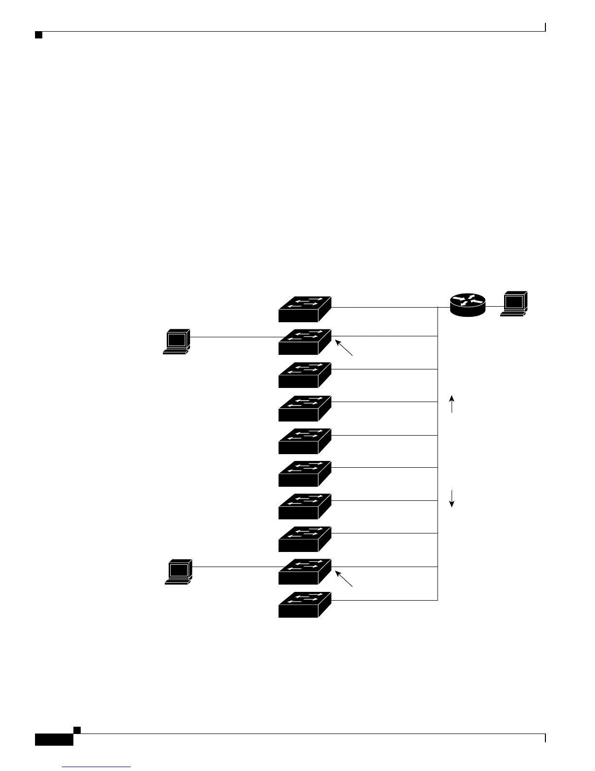
Figure 14-5 shows a network with a VMPS server switch and VMPS client switches with dynamic ports.
In this example, these assumptions apply:
• The VMPS server and the VMPS client are separate switches.
• The Catalyst 5000 series Switch 1 is the primary VMPS server.
• The Catalyst 5000 series Switch 3 and Switch 10 are secondary VMPS servers.
• The end stations are connected to these clients:
–
Catalyst 2950 Switch 2
–
Catalyst 3500 XL Switch 9
• The database configuration file is stored on the TFTP server with the IP address 172.20.22.7.
Figure 14-5 Dynamic Port VLAN Membership Configuration
Primary VMPS
Server 1
Secondary VMPS
Server 2
Secondary VMPS
Server 3
172.20.26.150
172.20.26.151
Trunk port
Catalyst 5000 series
172.20.26.152
Ethernet segment
(Trunk link)
172.20.26.153
172.20.26.154
172.20.26.155
172.20.26.156
172.20.26.157
172.20.26.158
172.20.26.159
Client
Client
End
station 2
End
station 1
TFTP server
Dynamic-access port
Dynamic-access port
Switch 10
Switch 9
Switch 8
Switch 7
Switch 6
Switch 5
Switch 3
Switch 2
Switch 1
Switch 4
172.20.22.7
30769
Trunk port
Router