6-50
Hardware Installation Guide for Cisco 4000 Series Integrated Services Routers
OL-32185-02
Chapter 6 Install and Upgrade Internal Modules and FRUs
Remove and Replace Cisco 4000 Series ISRs Power Supplies
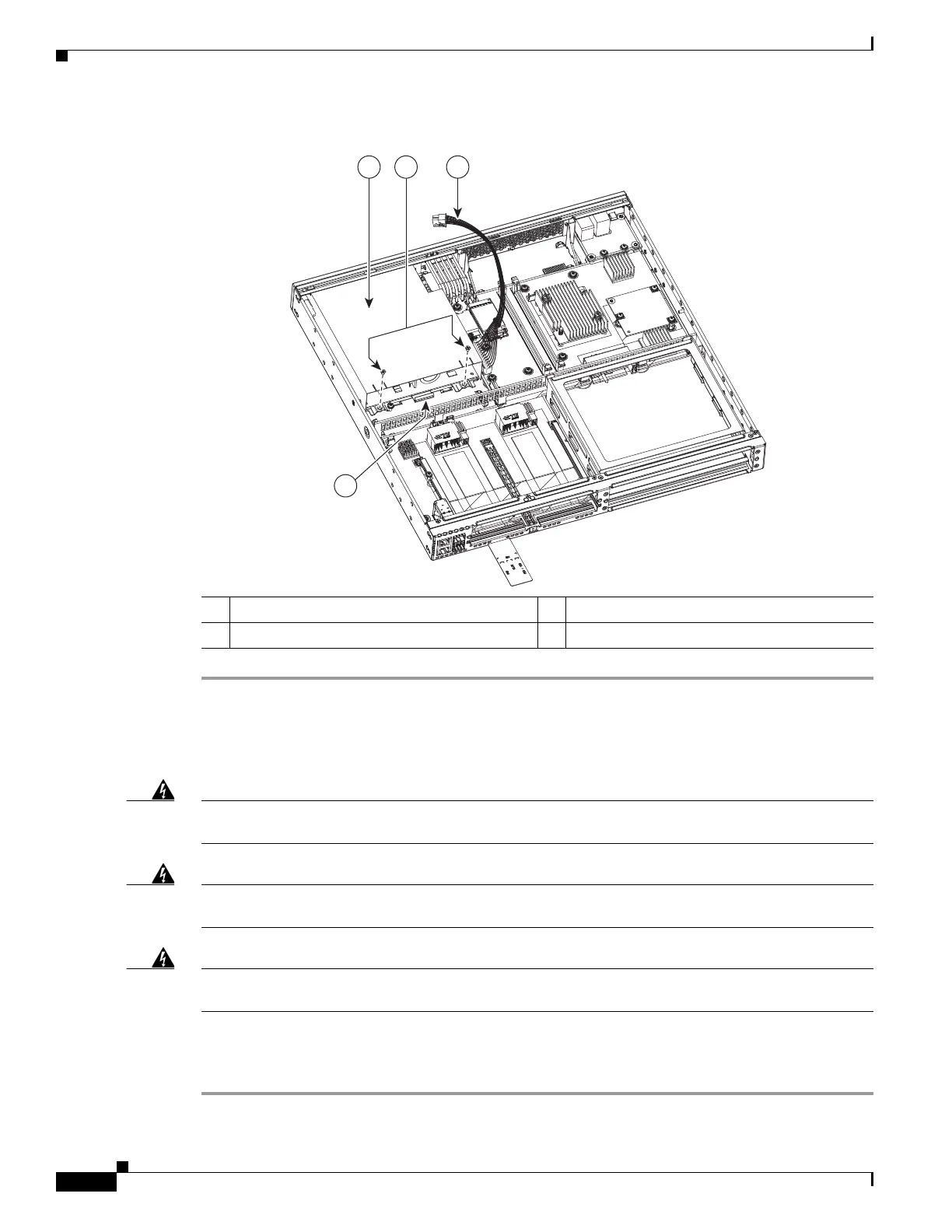
Figure 6-36 Cisco 4331 ISR Power Supply Module
Remove DC Input Power from Cisco 4331 ISR
Warning
Before performing any of the following procedures, ensure that power is removed from the DC
circuit.
Statement 1003
Warning
Only trained and qualified personnel should be allowed to install, replace, or service
this equipment.
Statement 1030
Warning
When installing or replacing the unit, the ground connection must always be made first and
disconnected last.
Statement 1046
This section describes how to remove a DC input power from Cisco 4331 Series ISR.
To remove a DC input power from Cisco 4331 ISR:
Step 1 Turn off the circuit breaker at the power source.
1 Power supply module 2 Screws
3 Power supply cable connector 4 Power supply module tab
 Loading...


