EasyManuals Logo

Cisco 4431 ISR User Manual

Cisco 4431 ISR
230 pages
To Next Page IconTo Next Page
To Previous Page IconTo Previous Page
Page #211 background imageLoading...
Page #211 background image
6-59
Hardware Installation Guide for Cisco 4000 Series Integrated Services Routers
OL-32185-02
Chapter 6 Install and Upgrade Internal Modules and FRUs
Replace a Fan Tray
Step 2 Completely loosen the three captive fan tray screws.
Step 3 Pull the fan tray out.
Step 4 Insert the replacement fan tray and tighten the three captive screws.
Step 5 Replace the bezel.
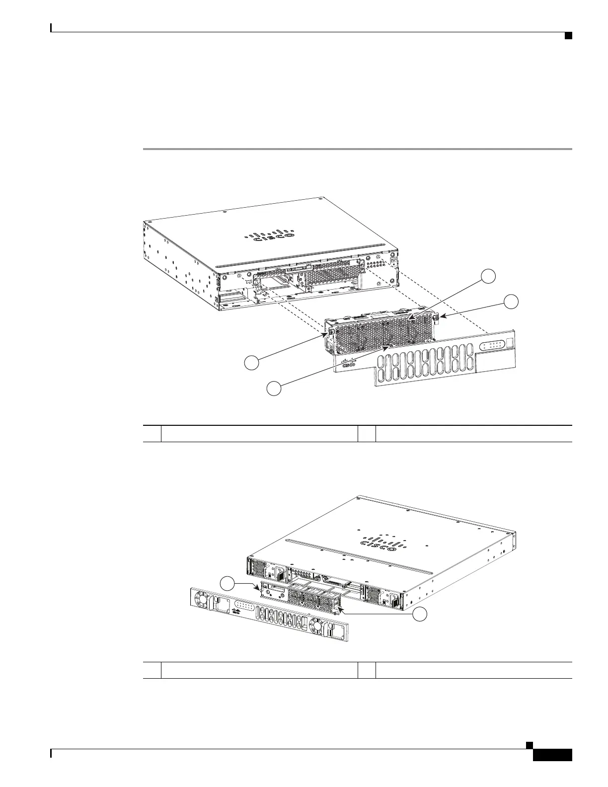
Figure 6-43 Cisco 4351 ISR4 Fan Tray
Figure 6-44 Cisco 4431 ISR Fan Tray
391825
1
1
2
1
1 Captive screws 2 Fan tray
385358
2
1

Table of Contents

Questions and Answers:

Question and Answer IconNeed help?

Do you have a question about the Cisco 4431 ISR and is the answer not in the manual?

Cisco 4431 ISR Specifications

General IconGeneral
Total onboard WAN or LAN 10/100/1000 ports4
RJ-45-based ports4
SFP-based ports2
NIM slots2
Enhanced service-module slots1
Rack height1 RU
Redundant power supplyOptional
Memory4 GB
Flash Memory4 GB
USB Ports2
Console Port1 x RJ-45
Auxiliary Port1 x RJ-45
Power SupplyAC 100-240V
Operating Temperature0 to 40°C
Storage Temperature-20 to 65°C
Humidity5% to 85% noncondensing
Dimensions (H x W x D)44.5 x 438.15 x 438.15 mm
Weight7.5 kg (16.5 lb)

Related product manuals