7-2
Firepower 7000 and 8000 Series Installation Guide
Chapter 7 Hardware Specifications
Firepower 7000 Series Devices
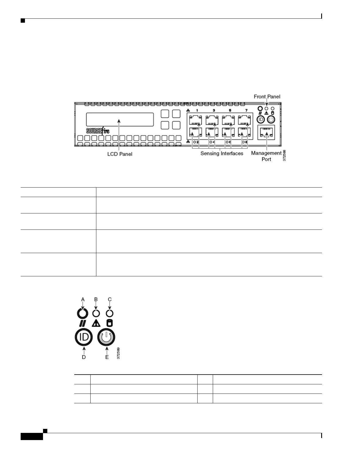
Firepower 70xx Family Front View
The front of the chassis contains the LCD panel, sensing interfaces, front panel, and management
interface.
Figure 7-1 Firepower 70xx Family (Chassis: CHRY-1U-AC; NEME-1U-AC) Front View
The following table describes the features on the front of the appliance.
.
Figure 7-2 Firepower 70xx Family Front Panel
Table 7-1 Firepower 70xx Family System Components: Front View
Feature Description
LCD panel Operates in multiple modes to configure the device, display error messages, and view system
status. For more information, see Using the LCD Panel on a Firepower Device, page 6-1.
Sensing interfaces Contain the sensing interfaces that connect to the network. For information, see Sensing
Interfaces, page 7-4.
10/100/1000 Ethernet
management interface
Provides for an out-of-band management network connection. The management interface is
used for maintenance and configuration purposes only and is not intended to carry service
traffic.
Front panel Houses LEDs that display the system’s operating state, as well as various controls, such as the
power button. For more information, see Table 7-11Firepower 7110 and 7120 Front Panel
Components, page 7-8.
Table 7-2 Front Panel Components
A Reset button D System ID button
B System status LED E Power button and LED
C Hard drive activity LED