3-6
Firepower 7000 and 8000 Series Installation Guide
Chapter 3 Deploying Firepower Managed Devices
Connecting Devices to Your Network
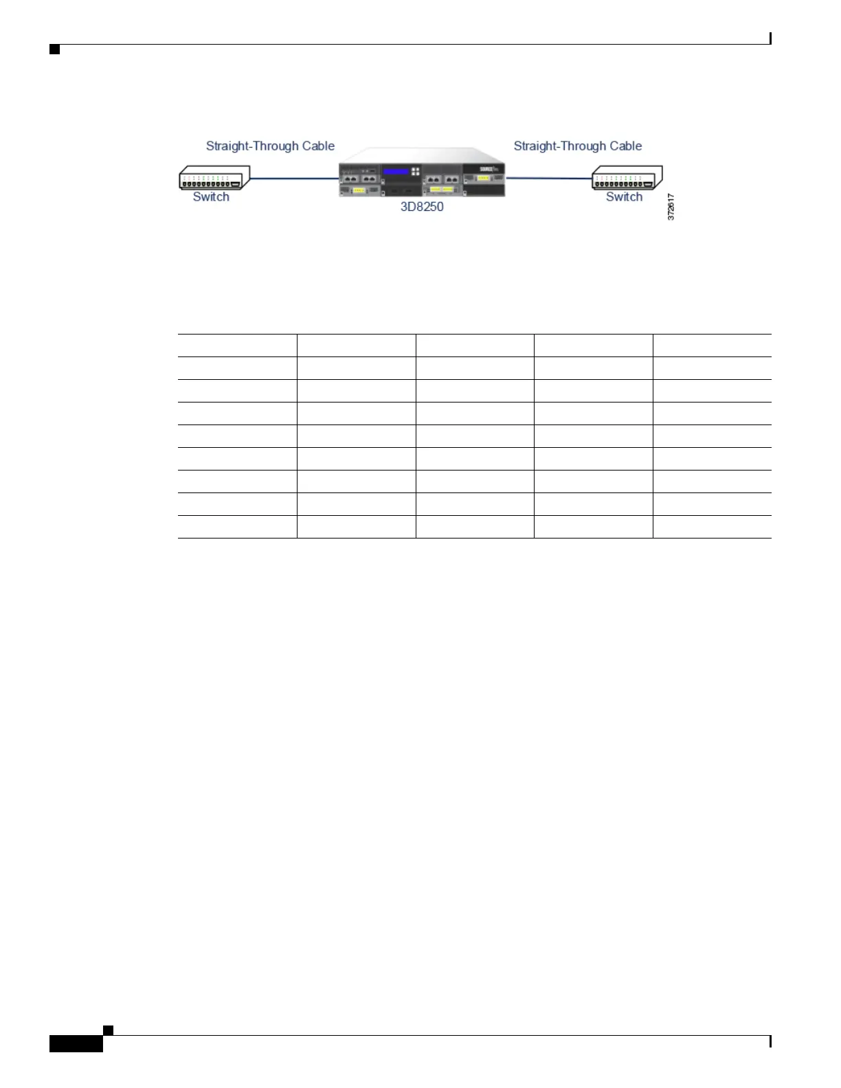
Figure 3-1 Crossover Bypass Connection Cabling
The following table indicates where you should use crossover or straight-through cables in your
hardware bypass configurations. Note that a Layer 2 port functions as a straight-through (MDI) endpoint
in the deployment, and a Layer 3 port functions as a crossover (MDIX) endpoint in the deployment. The
total crossovers (cables and appliances) should be an odd number for bypass to function properly.
Note that every network environment is likely to be unique, with endpoints that have different
combinations of support for Auto-MDI-X. The easiest way to confirm that you are installing your device
with the correct cabling is to begin by connecting the device to its two endpoints using one crossover
cable and one straight-through cable, but with the device powered down. Ensure that the two endpoints
can communicate. If they cannot communicate, then one of the cables is the incorrect type. Switch one
(and only one) of the cables to the other type, either straight-through or crossover.
After the two endpoints can successfully communicate with the inline device powered down, power up
the device. The Auto-MDI-X feature ensures that the two endpoints will continue to communicate. Note
that if you have to replace an inline device, you should repeat the process of ensuring that the endpoints
can communicate with the new device powered down to protect against the case where the original
device and its replacement have different bypass characteristics.
The Auto-MDI-X setting functions correctly only if you allow the network interfaces to auto-negotiate.
If your network environment requires that you turn off the Auto Negotiate option on the Network
Interface page, then you must specify the correct MDI/MDIX option for your inline network interfaces.
See Configuring Inline Interfaces in the Firepower Management Center Configuration Guide for more
information.
Special Case: Connecting Firepower 8000 Series Devices
When you register a Firepower 8000 Series managed device to your Firepower Management Center, you
must either use auto-negotiation on both sides of the connection, or set both sides to the same static speed
to ensure a stable network link. 8000 Series managed devices do not support half duplex network links;
they also do not support differences in speed or duplex configurations at opposite ends of a connection.
Table 3-1 Valid Configurations for Hardware Bypass
Endpoint 1 Cable Managed Device Cable Endpoint 2
MDIX straight-through straight-through straight-through MDI
MDI crossover straight-through straight-through MDI
MDI straight-through straight-through crossover MDI
MDI straight-through straight-through straight-through MDIX
MDIX straight-through crossover straight-through MDIX
MDI straight-through crossover straight-through MDI
MDI crossover crossover crossover MDI
MDIX crossover crossover straight-through MDI