7-34
Firepower 7000 and 8000 Series Installation Guide
Chapter 7 Hardware Specifications
Firepower 8000 Series Devices
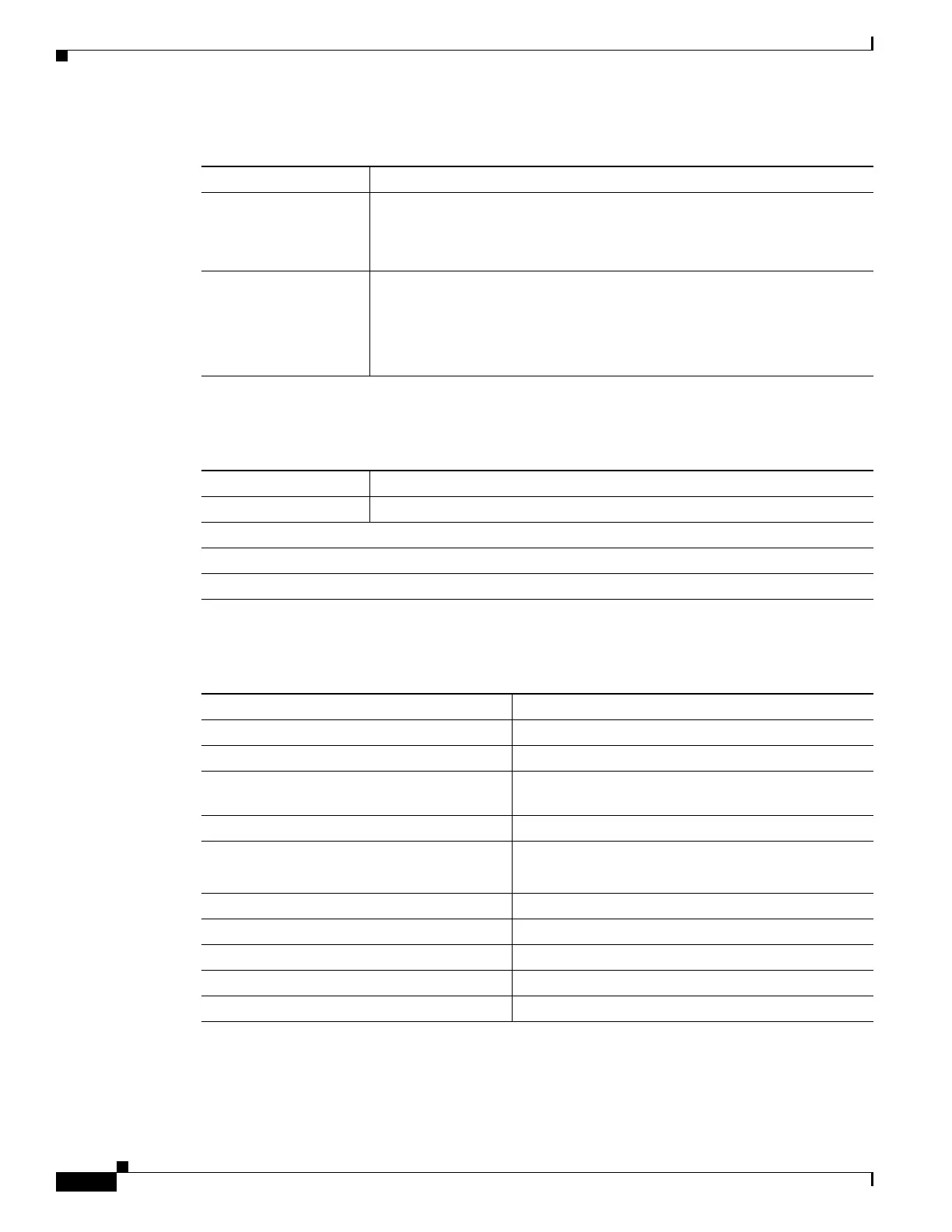
Use the following table to understand bypass LEDs on the fiber interfaces.
Use the following table to understand the optical specifications of the fiber interfaces.
Table 7-46 Fiber Link/Activity LEDs
Status Description
Top For an inline or passive interface:
• A blinking light indicates the interface has activity.
• No light indicates there is no activity.
Bottom For an inline interface:
• A light indicates the interface has activity.
• No light indicates there is no activity.
For a passive interface, the light is always on.
Table 7-47 Fiber Bypass LEDs
Status Description
Off The interface does not have link and is not in bypass mode.
Steady green The interface has link and is passing traffic.
Steady amber The interface has been intentionally brought down.
Blinking amber The interface is in bypass mode; that is, it has failed open.
Table 7-48 1000BASE-SX NetMod Optical Parameters
Parameter 1000BASE-SX
Optical connectors LC duplex
Bit rate 1000Mbps
Baud rate/encoding/tolerance 1250Mbps
8b/10b encoding
Optical interface Multimode
Operating distances 656 ft (200 m) for 62.5 µm/125 µm fiber
1640 ft (500 m) for 50 µm/125 µm fiber
Transmitter wavelength 770-860 nm (850 nm typical)
Maximum average launch power 0 dBm
Minimum average launch power -9.5 dBm
Maximum average power at receiver 0 dBm
Receiver sensitivity -17 dBm