The following figure shows the RJ-45 connector.
Figure 34: RJ-45 Connector
Pin 82Pin 11
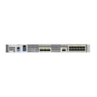
Install and Remove Transceiver Modules
This section provides the installation, cabling, and removal instructions for the Quad Small Form-Factor
Pluggable transceiver modules. Refer to the Cisco Optical Transceiver Handling Guide for additional details
on optical transceivers.
You must visually inspect the transceiver latch to ensure the transceiver module is not damaged so that when
it is inserted into the switch port, it will not damage the ports.
Note
Figure 35: 400-Gigabit QSFP-DD Transceiver Module
Hardware Installation Guide for Cisco 8500 Switches
56
Connect Switch to the Network
Install and Remove Transceiver Modules