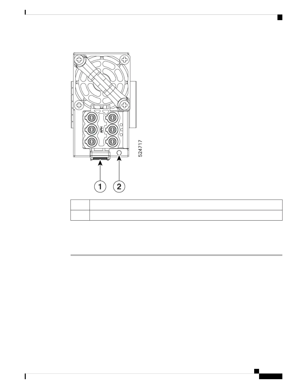
Figure 53: DC PSU
Tab1
LED2
Follow these steps to replace the power module.
Procedure
Step 1 If the power supply is connected to a AC or DC circuit, shut off the circuit at the circuit breaker.
Step 2 Disconnect the power module cable.
Step 3 Press the tab inward to unlatch the power module, and pull the handle to remove the power module.
Note
Do not use the pull tab to extract the entire PSU, as this may lead to tab breakage.
Step 4 Slide the new power module into the bay until it mates with its connector.
Note
If the power module does not go all the way into the slot, do not force it. Remove the power module and verify
that it is the correct type for your switch and in the correct orientation.
Step 5 Connect the power module cable.
Step 6 Verify that the Saf-D-Grid plug is plugged in completely to secure the built-in retaining latch.
Hardware Installation Guide for Cisco 8500 Switches
87
Replace Chassis Components
Replace Power Module