12
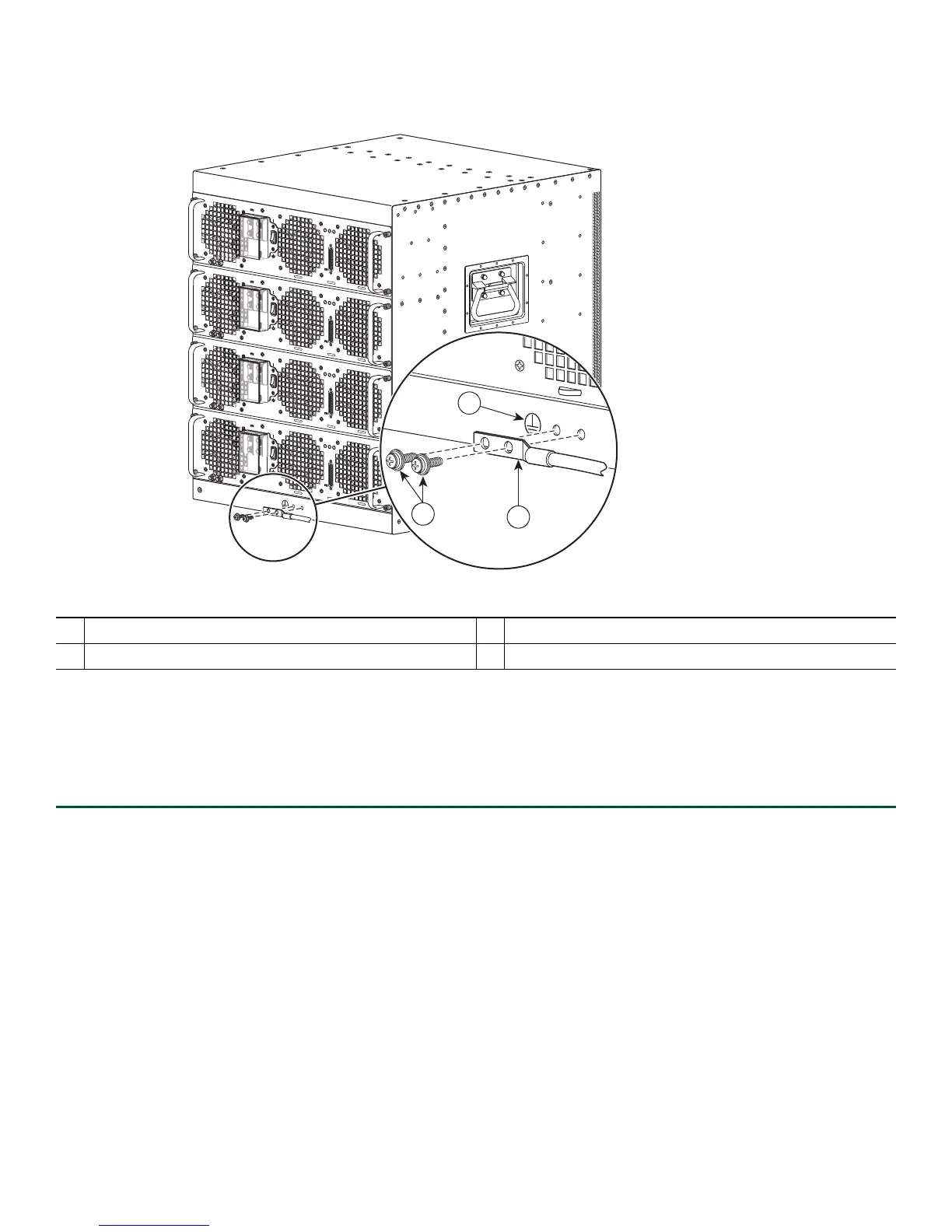
Figure 5 Attaching the Cisco ASR 1013 Router Ground Connection
OUTPUT INPUT FAN
FAIL OK O K
ALARMS
60V
1A MAX
This unit might have more than one power supply connection. All connections must be removed to de-energize the unit.
-48/-60V 40A
OUTPUT INPUT FAN
FAIL OK OK
ALARMS
60V
1A MAX
This unit might have more than one power supply connection. All connections must be removed to de-energize the unit.
-48/-60V 40A
OUTPUT
INPUT
FAN
FAIL
OK OK
ALARMS
60V
1A MAX
This unit might have more than one power supply connection. All connections must be removed to de-energize the unit.
-48/-60V 40A
OUTPUT
INPUT FAN
FAIL OK OK
ALARMS
60V
1A MAX
This unit might have more than one power supply connection. All connections must be removed to de-energize the unit.
-48/-60V 40A
might have more than one power supply connection. All connections must be r
2
1
3
253915
1
Chassis earth ground studs and lead wire
3
Chassis front rack-mount bracket and ear holes
2
Grounding screws Earth ground symbol
Step 6 In
sert the two screws through the holes in the grounding lug as shown in Figure 5.
Step 7 Use the Number 2 Ph
illips screwdriver to carefully tighten the screws until the grounding lug is held firmly to the
chassis. Do not overtighten the screws.
Step 8 Conn
ect the opposite end of the grounding wire to the appropriate grounding point at your site to ensure an adequate
chassis ground.
This completes the procedure for attaching a chassis ground connection. Go to the “Connect the Router to the Network” section
on page 12 for
information on attaching cables.
4 Connect the Router to the Network
This section provides information about cables and ports and attaching the router to the network.
• Console and Auxiliary Port Cable Connections, page 13
• Management Ethernet Port Cable Connection, page 13
• Connect the Shared Port Adapter Cables, page 14
• Using the Cable-Management Brackets, page 14

 Loading...


