17
• For DC input power cables, select the appropriate wire gauge based on the National Electrical Code (NEC) and local codes
for 40-amp service at nominal DC input voltage (–48/–60 VDC). Three pairs of cable leads, source DC (–) and source DC
return (+), are req
uired for each power distribution unit (PDU). These cables are available from any commercial cable
ven
dor. All input power cables for the chassis should have the same wire gauge and cable lengths should match within 10
percent of deviation. Each DC input power cable is terminated at the PDU by a cable lug. The cable lugs must be dual-hole,
and have a straight tongue. They must be able to fit over 1/4-inch terminal studs at 0.625-inch (15.88-mm) centers.
Note DC input power cables must be connected to the PDU terminal studs in the proper positive (+) and negative (–) polarity.
In some cases, the DC cable leads are labeled, which is a relatively safe indication of the polarity. However, you must
verify the polarity by measuring the voltage between the DC cable leads. When making the measurement, the positive
(+) lead and the negative (–) lead must always match the (+) and (–) labels on the power distribution unit.
• An earth ground cable is required for each DC PDU. We recommend that you use at least 6-AWG multistrand copper wire.
This wire is not available from Cisco Systems; it is available from any commercial cable vendor. The ground wire cable lug
should be dual-hole and able to fit over M6 terminal studs at 0.625 inch (15.88mm) centers. Recommended lug terminal
wire size Panduit part number:
–
LCD8-14A-L for 8AWG wire size
–
LCD6-14A-L for 6AWG wire size
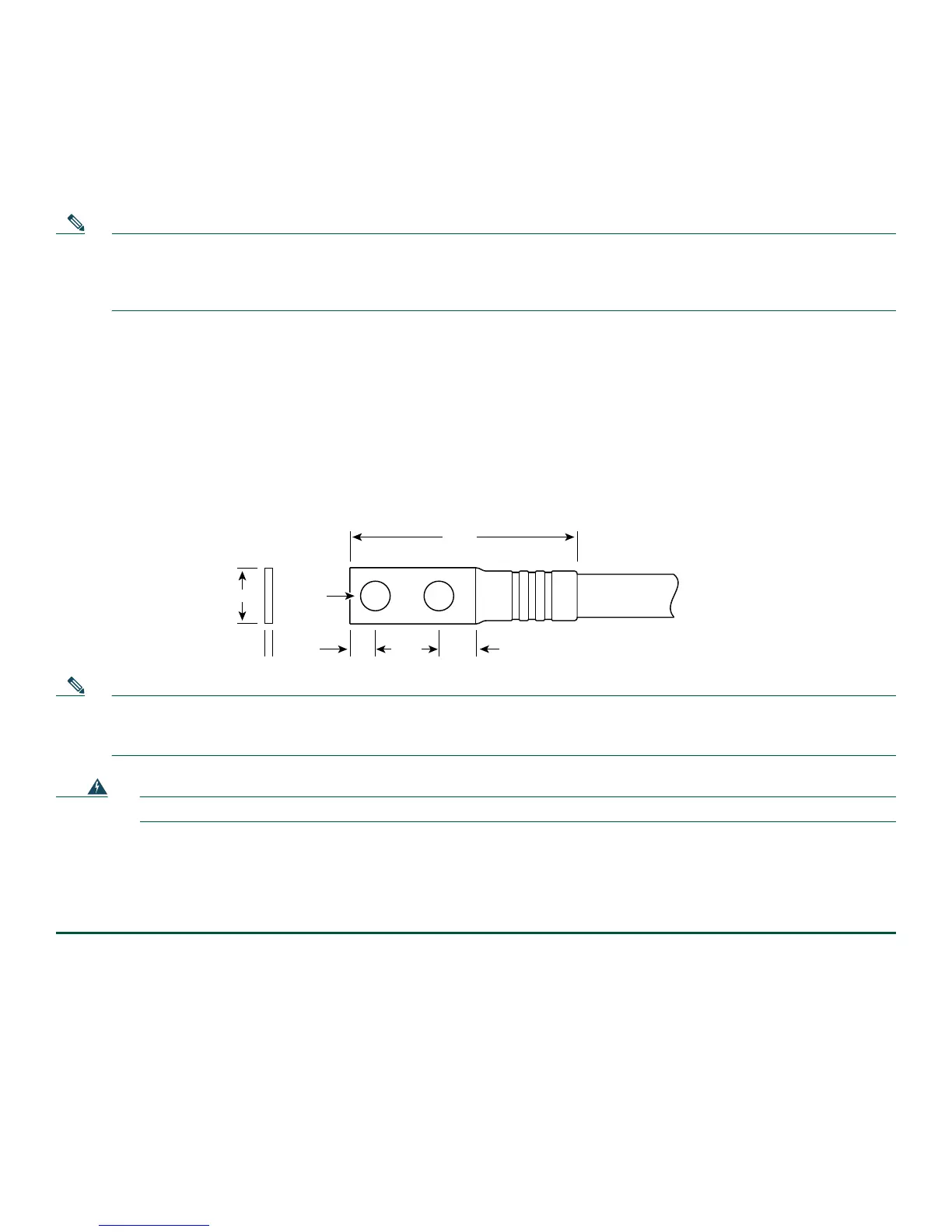
Figure 9 Cisco ASR 1013 Router DC Input Power Cable Lug
Crimp area
25527
2.24
0.48
0.08
0.25 0.370.63
End View
Ø 0.267
2 holes
All measurements in inches
Note To avoid hazardous conditions, all components in the area where DC input power is accessible must be properly
insulated. Therefore, before installing the DC cable lugs, be sure to insulate the lugs according to the manufacturer’s
instructions.
Warning
When you install the unit, the ground connection must always be made first and disconnected last.
Statement 1046
Installing the Cisco ASR 1013 Router DC Power Supply and Ground Lug
To install the grounding lugs on the DC power supply, follow these instructions. Figure 10 shows the location of the DC power
supply grounding stud.
Step 1 Make certain that the chassis ground is connected before you begin installing the DC power supply.
Step 2 Locate t
he stud on the DC power supply for the GND connection which must be connected first and follow these steps:
a. Usin
g the grounding lug, replace the washers and Kepnut screw in the following order.
- Flat washer
- Grounding cable lug
- Kepnut screw
b. T
ighten the Kepnut screws on the power supply studs.
Step 3 T
ighten the Kepnut screw (use the screwdriver to tighten the ground screw in the terminal block to a torque of
20+/–2 in-lbs / 2 per.)
to complete the installation.

 Loading...


