15
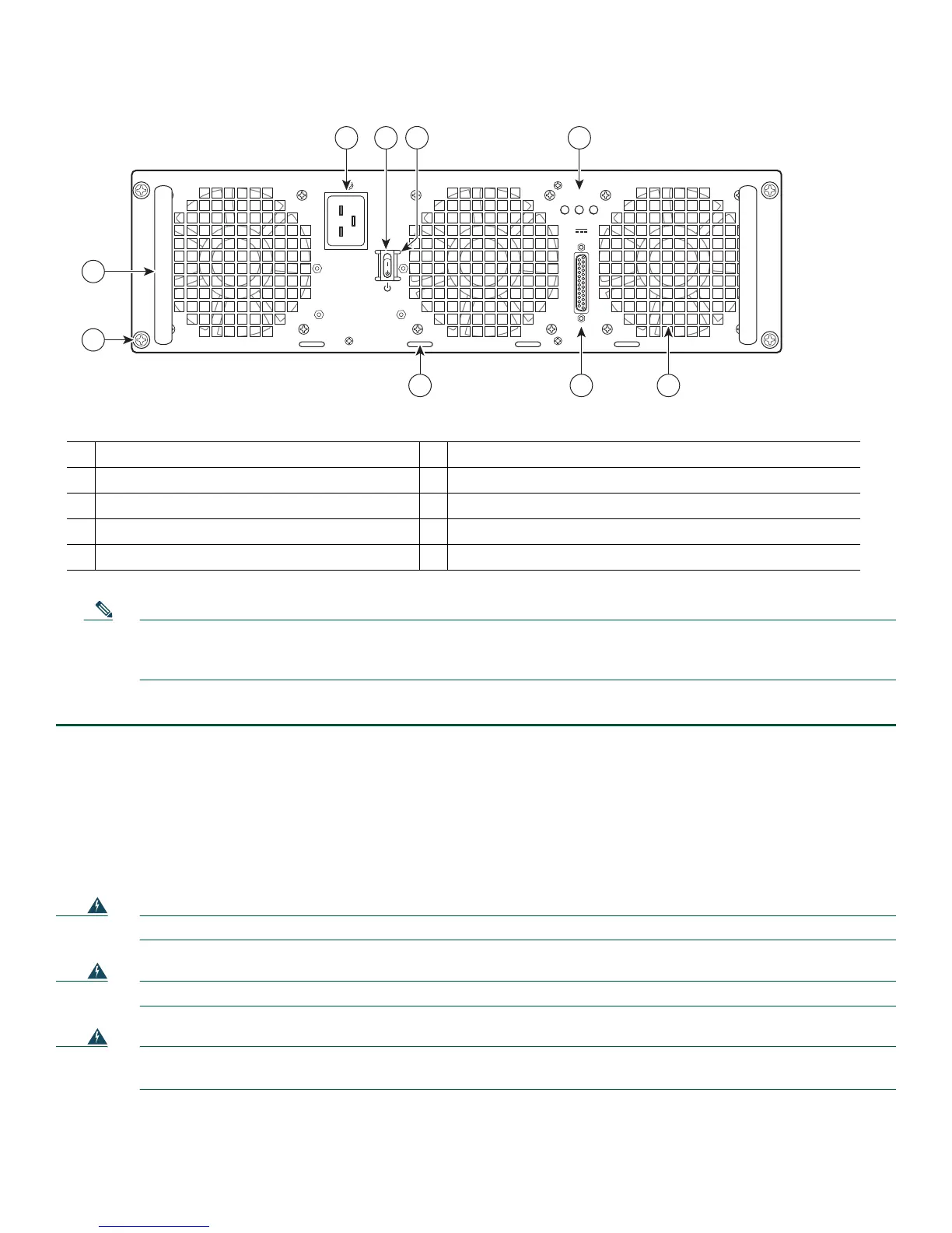
Figure 7 Cisco ASR 1013 Router AC Power Supply Power
253916
OUTPUT INPUT INPUT
FAIL OK OK
ALARMS
60V
1A MAX
100-240V~ 16-7A
50-60HZ
This unit might have more than
one power supply connection.
All connections must be removed
to de-energize the unit.
2 13
4
5
6 7
9
8
1
AC power supply fan
6
AC power inlet
2
DB-25 alarm connector
7
AC power supply Standby switch
3
Tie-wrap tab
8
Protective shielding on both sides of the Standby switch
4
AC power supply captive screw
9
AC power supply LEDs
5
AC power supply handle
Note Shielded cables must be used to connect to the DB-25 alarm connector on both the AC and DC power supplies in
order to comply with FCC/EN55022/CISPR22 Class A emissions requirements. See
How Cisco ASR1000-RP Alarm
Monitoring Works, page 20.
Step 3 Plug
the AC power supply cable into the AC power source.
This completes the procedure for connecting AC-input power.
Connect DC Power to the Cisco ASR 1013 Router
This section provides instructions for installing the DC power supply into the Cisco ASR 1013 Router. Read the safety warnings
before you begin.
Warning
Installation of the equipment must comply with local and national electrical codes.
Statement 1074
Warning
Never install an AC power module and a DC power module in the same chassis.
Statement 1050
Warning
When installing or replacing the unit, the ground connection must always be made first and disconnected last.
Statement 1046
 Loading...


