21
Note The Cisco ASR 1013 Router has four power supplies and two power supply zones. There are two power supplies
for power zone 0 and two power supplies for power zone 1 (Do not mix AC and DC power supplies). The two
zones are split up with the numbering scheme Zone 0 = PS0 and PS1 and for Zone 1 = PS2 and PS3. You must have
one power supply running at all times from each power supply zone and two power supplies from each power
supply zone to support redundancy. Four power supplies, either AC power supplies or DC power supplies, are
accessed from the rear of the router. In the Cisco ASR 1013 Router, at least one PEM in each 1+1 redundant power
supply zone must be functioning to power the zone and both zones be functional. In the event of a single fan failure,
the remaining fans are sufficient to cool the entire chassis although fan speed may have to be increased. For detailed
information regarding power supply zones, refer to the Cisco ASR 1000 Series Hardware Installation Guide.
Step 3 Listen for the fans; y
ou should immediately hear them operating.
Step 4 During the
boot process, observe the power LEDs. The power LED should be green on all boards. The Status LED lights
yellow to indicate booting and then green when IOS is running.
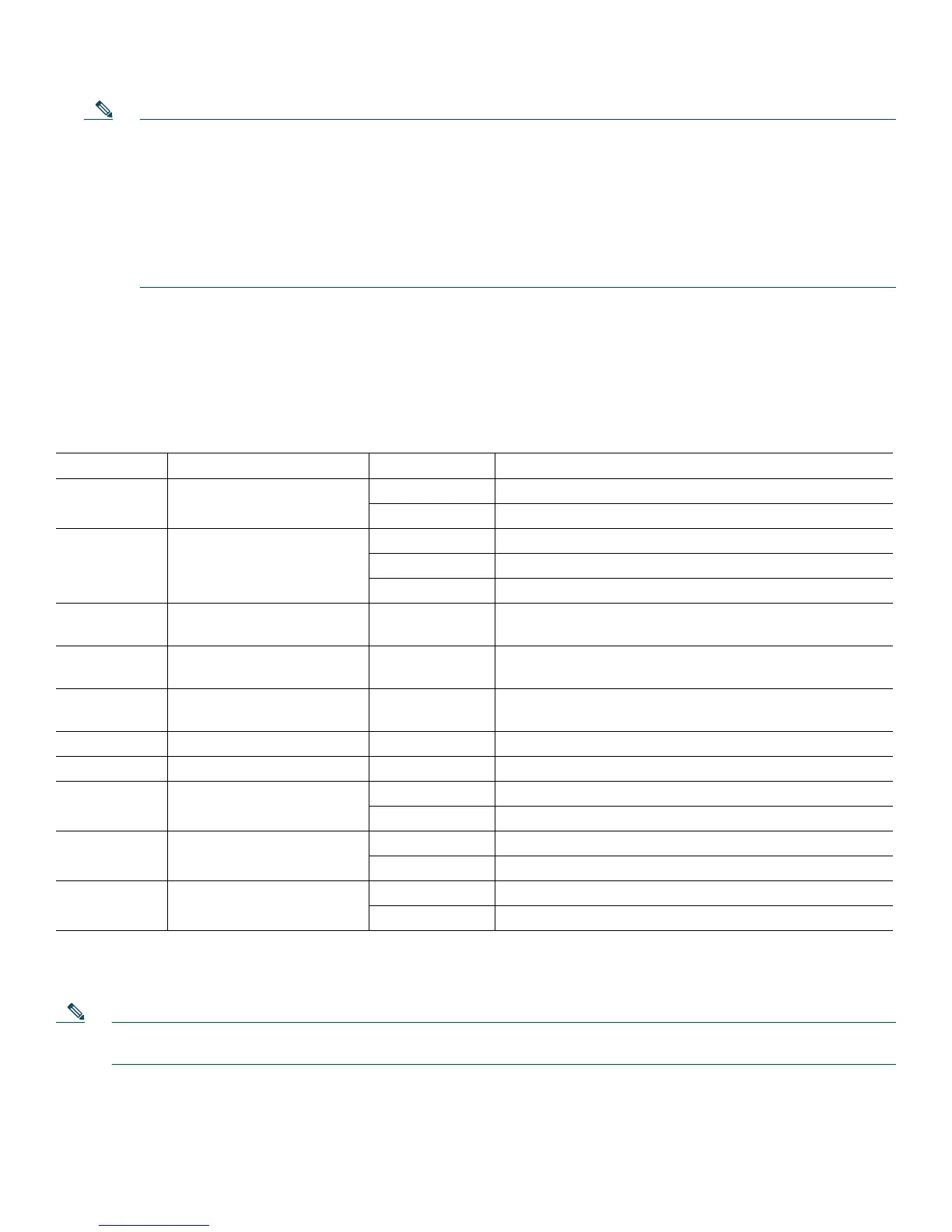
Table 1 provides information about the LEDs as the system starts.
Ta b l e 1 Cisco ASR 1013 Router LED Activity
LED Label LED Color In the Power Up State -Behavior Description
PWR Power Solid green All power requirements are within specification
Off Off, the router is in standby mode.
STAT System status Solid green Cisco IOS has successfully booted.
Yellow BOOT ROM has successfully loaded.
Red System failure.
ACTV Active Green Lit when this is the active ASR 1000 Series route processor
(C
isco ASR1000-RP1 or Cisco ASR1000-RP2).
STBY Standby Yellow Lit when this is the standby ASR 1000 Series route
pr
ocessor.
CRIT Critical Solid red Critical alarm indicator. This is on at power up, turned off
by soft
ware.
MAJ Major Solid red Major alarm indicator.
MIN Minor Amber Minor alarm indicator.
DISK HD Internal Hard Drive Flashing green Active indicator.
Off No activity.
DISK USB External USB FLASH Flashing green Active indicator.
Off No activity.
DISK BF Internal FLASH (BootDisk) Flashing green Active indicator.
Off No activity.
During the boot process, observe the system LEDs. The STAT LED comes on
immediately as yellow, then turns to green
when the Cisco IOS is booted. The shared port adapter LEDs go on and off irregularly.
Note The system boots differently depending on the configuration that ships with your system. This output is only an
example of some output that can display.
Step 5 Observe the initialization process. When the system boot is complete (a few seconds), the Cisco ASR 1000 Series route
processor begins to initialize. The console screen displays a script and system banner similar to the following:

 Loading...


