34
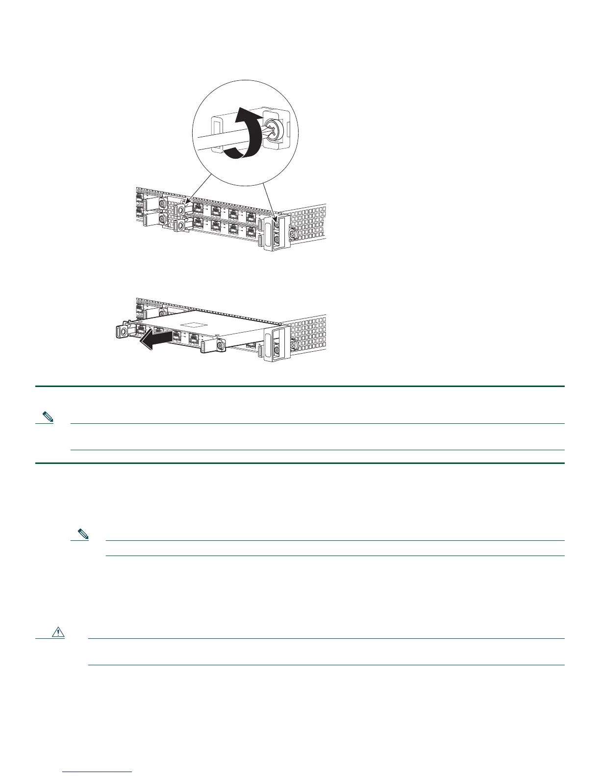
Figure 15 Installing and Removing a SPA Into and From a SIP
STATUS
STATUS
C/A
C/A
A/L
A/L
3
3
SPA-4XOC3-POS
SPA-4XOC3-POS
0
1
2
C/A
C/A
S
TATUS
STATUS
0
A/L
A/L
C
/A
C/A
A/L
A/L
C
/A
C/A
A/L
A/L
C
/A
C/A
A/L
A/L
1
2
3
3
SPA-4XOC3-POS
SPA-4XOC3-POS
ASR
1000-SIP10
PWRSTATUS
STATU
S
STAT
US
C
/A
C/A
A/L
A/L
3
3
SP
A-4XO
C3-POS
SP
A-
4XOC3-POS
C/A
STATUS
STATUS
0
A/L
C
/A
A/L
C/A
A/L
C/A
A/L
1
2
3
SPA-4
X
OC3-POS
ASR1000-SIP10
PWRS
TATUS
SPA-4XOC3-POS
0
1
2
3
C/A
A/L
C/A
A/L
C/A
A/L
C/A
A/L
281171
Step 4 After the SPA is properly seated, fasten the SPA in place with the captive installation screws on either side of the SPA.
Note The shared port adapter ships installed. These instructions are provided for future use. Cabling information is included
with the specific shared port adapter documentation.
Step 1 Attach an ESD wrist strap between you and an unpainted chassis surface.
Step 2 If a
ttached, remove any cables from the SPA.
Step 3 Before removing
any shared port adapter, shut down the interface so that there is no traffic running through the shared
port adapter when it is removed.
Note Removing a shared port adapter while traffic is flowing through the ports can cause system disruption.
Step 4 Remove the shared port adapter from the chassis slot. Unfasten the captive installation screws on either side of the SPA.
Step 5 Grasp the h
andle and pull the shared port adapter or blank shared port adapter from the router.
Step 6 Locate the shared
port adapter slot guides inside the Cisco ASR 1013 Router. They are near the top, and are recessed
about one-half inch.
Caution The shared port adapter must slide into the slot guides under the chassis lid. Do not allow the shared port adapter
components to come in contact with the system board or the shared port adapter could be damaged.
Step 7 Carefully slide the shared port adapter into the shared port adapter slot and seat it. When installed, the shared port
adapter input/output panel should be flush with the face of the router.

 Loading...


