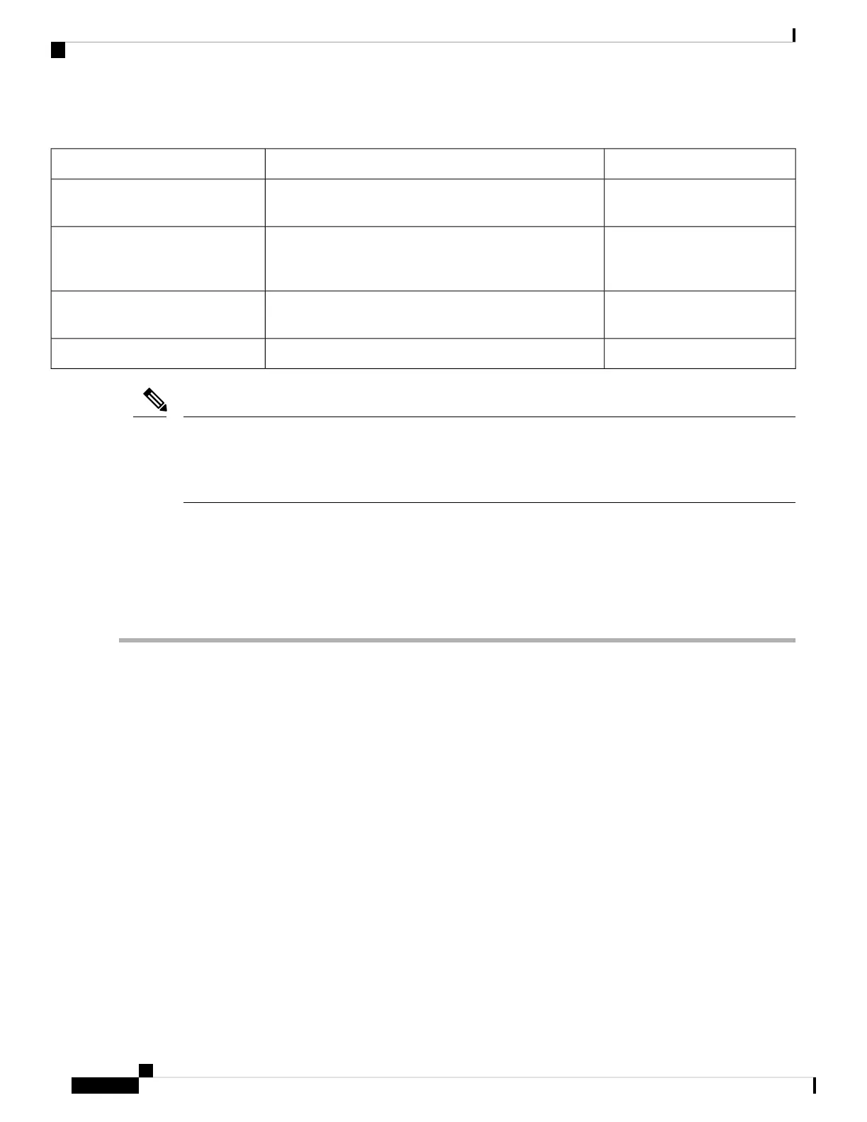
Table 57: show Commands to Display SPA Information
ExampleType of Information ProvidedCommand
show controllers sonet 0/1/0/1Network link status, register contents, and controller chip
errors.
show controllers type
rack/slot/subslot/port
show interface serial
0/1/0/0/1/1:0
Line status and data link protocol status for a particular SPA
port. Statistics about data traffic sent and received by the
port.
show interfaces type
rack/slot/subslot/port
show diag 0/1/CPU0SPA type in that slot, number of ports, hardware revision,
part number, and EEPROM contents.
show diag rack/slot/subslot/
show versionCisco IOS XR software version and boot images.show version
When a SIP is moved to a new slot, the system recognizes the new interfaces but leaves them in the shutdown
state until you configure them and change their state to up. When a new SIP is inserted into a slot where a
SIP previously resided, provided you reinstall the SPAs and interfaces cables in the same configuration as in
the previous SIP, the interfaces will come up in the same state as though you reinserted the old SIP.
Note
The following sample display shows the events logged by the system as you insert a new SIP in module slot
3.
Router#
18:05:25: %LINEPROTO-5-UPDOWN: Line protocol on Interface 0/POS3/1, changed state to down
Use the following procedure to verify that the SIP is installed correctly:
Step 1 Observe the console display messages and verify that the system discovers the SIP, while the system reinitializes each
interface, as follows:
• If you installed a new SIP, the STATUS LED should be on (green). The system should recognize all new interfaces
but leave them configured as down .
• If you replaced a SIP, the STATUS LED should be on (green). The interfaces will come up in the same state as
though you reinserted the old SIP.
Step 2 Verify that the STATUS LED on the SPA goes on (is green) and remains on after the reinitialization is complete. If the
STATUS LED remains on, proceed to Step 5. If the STATUS LED does not remain on, proceed to Step 3.
Step 3 If the STATUS LED on a SPA fails to go on, the SPA or the SIP might not be fully seated even if the SPA lock is in the
locked and horizontal position.
• Remove the SPA from the SIP.
• Inspect the SPA. Verify there are no bent pins or parts and that there is nothing lodged in the two devices that could
prevent a good connection.
• Insert the SPA in the SIP by sliding the SPA all the way in the SIP until the SPA is firmly seated in the SPA interface
connector. When fully seated in the SIP, the SPA might be slightly behind the SIP faceplate.
The SPA will slide easily into the slot if it is properly aligned on the tracks. If the SPA does not slide easily,
do NOT force it. Remove the SPA and reposition it, paying close attention to engaging it on the tracks.
Note
Cisco ASR 9000 Series Aggregation Services Router SIP and SPA Hardware Installation Guide
98
Installing and Removing a Shared Port Adapter
Using show Commands to Display SPA Information
 Loading...


