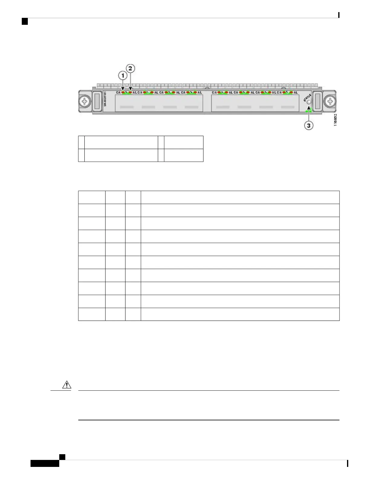
Figure 23: 8-Port Channelized T1/E1 SPA Faceplate
STATUS LED3C/A (Carrier/Alarm) LED1
A/L (Active Loopback) LED2
The 8-Port Channelized T1/E1 SPA LEDs are described in the following table.
Table 23: 8-Port Channelized T1/E1 SPA LEDs
MeaningStateColorLED Label
Port is not enabled by software.OffOffC/A
Port is enabled by software, and there is a valid T1 or E1 signal without any alarms.OnGreen
Port is enabled by software, and there is at least one alarm.OnAmber
Port is not enabled by software.OffOffA/L
Port is enabled by software, loopback is off.OnGreen
Port is enabled by software, loopback is on.OnAmber
SPA power is off.OffOffSTATUS
SPA power is on and good, and SPA is being configured.OnAmber
SPA is ready and operational.OnGreen
8-Port Channelized T1/E1 SPA Interface Specifications
The E1 interface on the 8-Port Channelized T1/E1 SPA uses RJ-48c receptacles for E1 (120-Ohm) cables
with RJ-45 connectors. You can use all ports simultaneously. Each E1 connection supports interfaces that
meet G.703 standards. The RJ-45 connection does not require an external transceiver. The E1 ports are E1
interfaces that use 120-ohm shielded twisted pair (STP) cables.
Shielded twisted pair (STP) T1/E1 cables must be used to comply with EN55022/CISPR22 Class A emissions
requirements. For revisions 73-8358-05 through 73-8358-08 Shielded Twisted pair (STP) T1/E1 cables must
be used to comply with FCC Class A emissions requirements.
Caution
Cisco ASR 9000 Series Aggregation Services Router SIP and SPA Hardware Installation Guide
34
Overview: Cisco ASR 9000 Series Router Shared Port Adapters
8-Port Channelized T1/E1 SPA Interface Specifications

 Loading...


